2 Wiring and Components
Page 4 Mk8 EGA Set-Up and Trim Guide 12.04.2016
2 WIRING AND COMPONENTS
2.1 Flying Lead Wiring Diagram
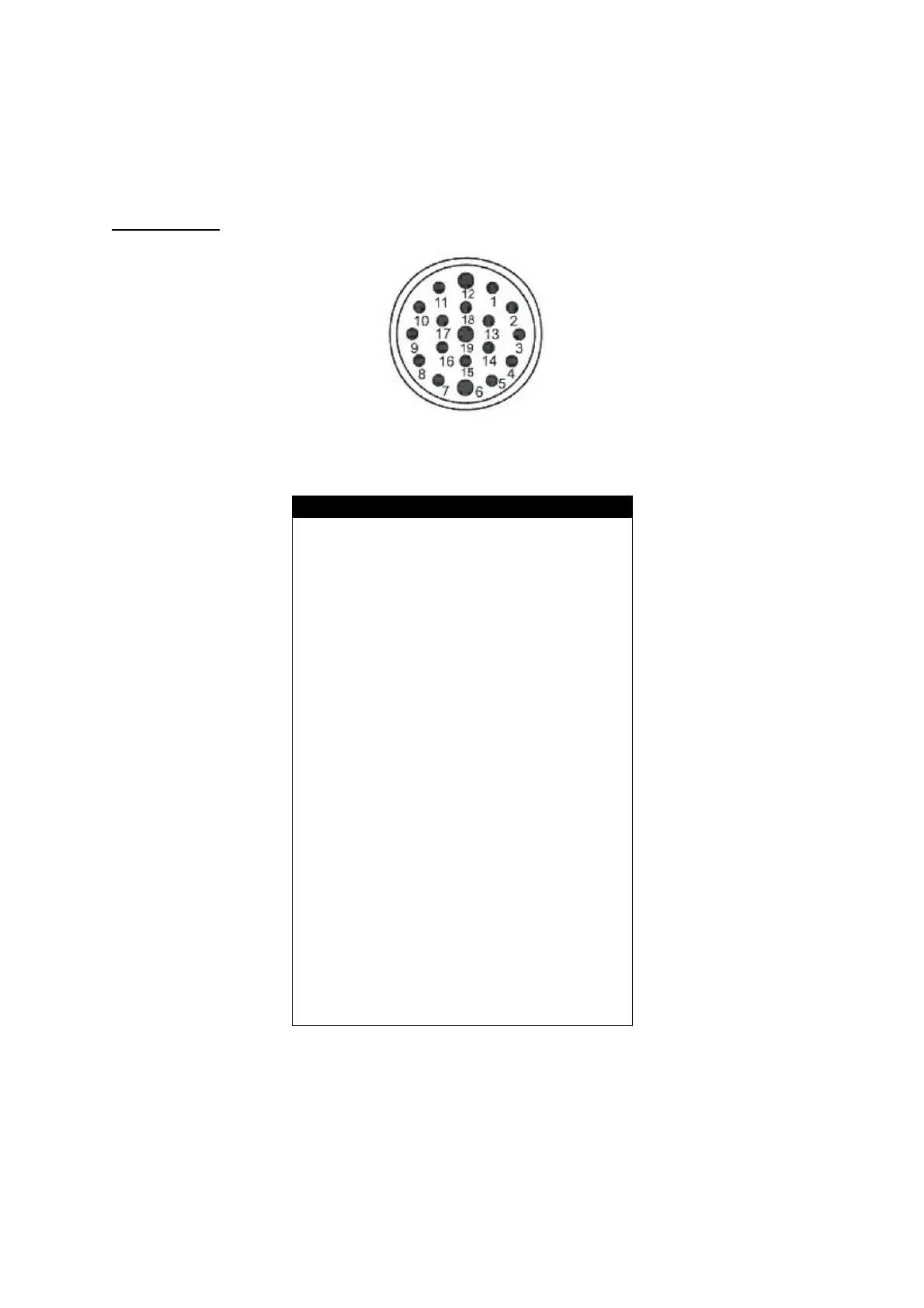
Data Connector
Figure 2.1.i Data Connector – Insert Pin Mating View
Pin Number Assigned function
1 4-20 mA Output Channel (1+)
2 4-20 mA Output Channel (2+)
3 4-20 mA Output Channel (3+)
4 4-20 mA Output Channel (4+)
5 4-20 mA Output Channel (5+)
6 4-20 mA Output Channel (6+)
7 4-20 mA Output Common (-)
8 Fuel 1 Select Input
9 Fuel 2 Select Input
10 Fuel 3 Select Input
11 Fuel 4 Select Input
12 Fuel Select Input common
13 MM Comms (-)
14 MM Comms (+)
15 DTI Comms (-)
16 DTI Comms (+)
17 4-20mA Input (-)
18 4-20mA Input (+)
19 Not Connected
Note: The data cable should be screened at the MM/DTI end and connected all the way to the EGA
plug; the screen from the flying lead provided should be connected to the data cables that connect to
the MM/DTI.
Note: Fuel Select Inputs in standalone mode are low voltage. To select a fuel, put a link on the ‘Fuel X
Select Input’ to the Fuel Select Input Common e.g. to select fuel 1, link pin 8 to pin 12 to select fuel 1 in
standalone mode.
 Loading...