Pilot Operating Handbook
Cavalon
SECTION 7
SYSTEM DESCRIPTION
AutoGyro_POH_Cavalon 915iS Revision 1.0 – Issue Date 08.MAY.2019 7-21
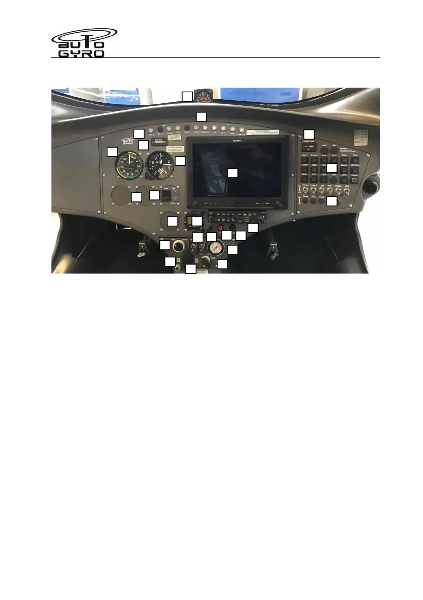
Panel Layout – Glass Cockpit – Garmin G3X
1 – Water temperature indication 15 – LANE switches
2 – Magnetic compass 16 – Trim/brake pressure gauge
3 – Warning lights 17 – 12V power receptacle (if installed)
4 – Lateral trim indicator 18 – Master/starter switch
5 – Air speed indicator 19 – Audio in (if installed)
6 – Altimeter 20 – Pre-rotator overdrive/override
7 – Cut-out 57mm / 2 ¼” for optional inst. 21 – Garmin G3X Glass Cockpit
8 – Garmin comms panel 22 – Hour meter
9 – VP Prop control 23 – Circuit Breaker Panel
10 – Alternative transponder location 24 – Switches
11 – Vent knob Note that the Garmin transponder is built in.
12 – Fan
13 – Radio (if installed)
14 – Pneumatic mode selector
Garmin equipment note.
1. When starting the panel, the radio is turned ON with the Garmin Comms panel OFF. After
radio boot-up, then turn the Garmin comms ON.
2. The transponder interface is via the Garmin G3X panel. The transponder device is
located under the left seat.
Read the operation manuals!
1
2
3
4
5
6
7
8
10
11
13
14
15
16
17
19
12
20
21
22
23
24
18
9