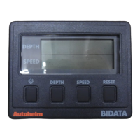
ST30 Bidata Instrument
6 ST30 Bidata Service Manual 83009-2
Z171
Chapter 3. PCB Details
3.1 PCB Setting
The ST30 Bidata and Depth instrument PCBs are the same. Therefore, it is
necessary to ensure that the PCB is correctly set after fitting to a unit.
1. Connect the instrument to a 12 volt power supply
2. Observe the display. If the PCB is correctly set the display will show
speed and depth information
3. If the display shows unintelligible information the PCB is set for use as
a depth instrument.
Note: The PCB can be reset as a depth unit as follows.
1. Turn the power supply to the instrument off
2. Press and hold down all four keys
3. Turn the power supply on and observe the display
4. Depth and speed only information should now be displayed.
3.2 Input/Output Signals (refer to Figure 2 Circuit Diagram)
Wire colour Circuit diagram Description
reference
Red P1/P2 +12V nominal dc supply
Yellow P3/P4 SeaTalk data. Intermittent streams
of +12V (nominal) pulses.
Screen P5/P6 0V supply and signal return
Red P7 Speed transducer supply.
12V dc nominal.
Green P8 Speed transducer – Log signal
Screen P9 Speed transducer, 0V
Red P10 Depth +, echoes from transducer
Black P11 Depth, 0V