EasyManua.ls Logo

AUTOHELM Masterview ST80 - User Manual

AUTOHELM Masterview ST80
22 pages
Print Icon
To Next Page IconTo Next Page
Loading...
Z211 ST80 Masterview Service Procedures
D2601-1
masterview
Z211Z211
Z211Z211
Z211
ST80 Masterview
ST80 Masterview Service Manual 83028-1 1
Question and Answer IconNeed help?

Do you have a question about the AUTOHELM Masterview ST80 and is the answer not in the manual?

Overview

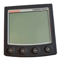
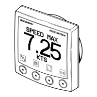
The ST80 Masterview Head (Product Code Z211) is a multifunction instrument designed to display SeaTalk data in both alphanumeric and graphic formats. It serves as a central display unit within a SeaTalk system, providing users with a comprehensive overview of various marine data.

Function Description

The Masterview processes external and internal inputs, including SeaTalk data and signals from a custom-designed Autohelm ASIC (Application-Specific Integrated Circuit). The microprocessor within the unit generates appropriate commands and responses based on this data.

Key functions include:

  • SeaTalk Data Conversion: The ASIC converts duplex SeaTalk data into transmit and receive formats (STDATA) for the microprocessor. Conversely, it converts data from the microprocessor (DATA Tx) into 12V SeaTalk format for outgoing signals.
  • Data Display: The primary function is to display SeaTalk data on an LCD screen. This includes both alphanumeric information and graphic representations.
  • Keypad Interaction: The unit features a keypad for user input. Scan signals are sent to the keypad switches (SW1-4), and illumination for keypad LEDs (1-8) is controlled through drive transistors (TR5, TR6).
  • LCD Contrast Control: Contrast is managed by signals applied to a negative voltage generator (IC16) via a current amplifier/integrator (TR3, TR12, C8). IC16 generates VEE, which powers the row and column LCD drivers. Contrast control signals (V1-V6) are produced by a resistor network (R17-21) and the current amplifier (IC10), then applied to LCD row driver IC9 and column drivers IC5, 6, 7, 8.
  • LCD Driver Control: Control signals (D_RES, D/L, R/W) and column/row address signals (L0-L7) are supplied to LCD decoder/drivers (IC5, 6, 7, 8, 9). Row driver IC9 also generates internal and column driver control signals.
  • Electroluminescent Panel Brightness Control: Brightness signals for the EL panel are filtered by an RC network (R64, C45) and applied to a driver circuit (TR7, 20, 21, 22, 23).
  • Beeper Functionality: The ASIC generates beeper drive signals, and the beeper frequency is set by external R-C networks.
  • Power Monitoring and Shutdown: The ASIC monitors VHELD, VUNREG, and VCC. In the event of supply failure or intentional switch-off, it issues a PWR_FAIL signal, triggering an orderly software shutdown.
  • Watchdog Timing: The ASIC incorporates watchdog timing (WDOG) functionality, with its interval set by external R-C networks.
  • Reset Functionality: The ASIC provides a reset (RST) signal.

Important Technical Specifications

  • Power Supply: Nominal 12V DC, entering via P1 or P4. Varistor protection is included across the supply and OV IN (P2, P5) to guard against power surges and voltage spikes.
    • +5V (Vcc) is provided by IC14, a 5V regulator.
    • Reverse diode D1 ensures a floating OV for the circuitry.
  • Microprocessor: IC13 operates at a clock rate of 16MHz, determined by crystal XL1.
  • Data Storage:
    • Programs and 'fixed' data (factory-set default values) are stored in FLASH MEMORY IC2.
    • Other data is stored in RAM IC15, which is supplied with a maintaining voltage from battery B1 during power loss to preserve data.
    • TR18 (FLASH MEMORY) and TR11 (RAM) supply VCC during normal operation. If power fails, the ASIC (IC4) issues a reset signal, cutting off TR18 via TR17. Battery B1 then supplies RAM IC15 via diode D16.
  • Connectors:
    • Pin Nos. 1 & 4: +12V (Nominal 12V dc)
    • Pin Nos. 2 & 5: OV (OV Screen)
    • Pin Nos. 3 & 6: SeaTalk (Irregular Pulse Trains, nominal 12V amplitude)
  • CE Marking: The equipment carries the European CE mark. For maintenance, only Autohelm-supplied or approved parts and components should be used to maintain CE compliance.

Usage Features

  • Multifunction Display: The Masterview can display various SeaTalk data types in both alphanumeric and graphic formats, offering flexibility in how information is presented to the user.
  • Keypad Control: User interaction is primarily through the integrated keypad, allowing for navigation and selection of display modes or settings.
  • No Operational Calibration Required: For testing purposes, no specific operational setup or calibration is required, simplifying the diagnostic process.

Maintenance Features

  • Disassembly and Assembly Procedures: Detailed instructions are provided for separating the front and rear covers, handling the PCB/LCD subassembly, and reconnecting components. Special tools like the ST80 Case Separation Tool (T041) are recommended for safe disassembly.
  • Preliminary Inspection: Before testing, a thorough visual inspection is recommended to check for physical damage, water ingress, PCB damage (especially power supply areas), and connector corrosion.
  • Functional Test Flowchart: A comprehensive flowchart guides technicians through a series of tests, including power-up checks, keypad verification, display of operational screens, version number checks, and display pattern tests. This systematic approach helps in diagnosing faults.
  • Test Equipment Connection: Specific test equipment, including a 12V 5A power supply, ST80 power and daisychain cables, and a known good ST80 remote keypad (or another ST80 instrument), is required for functional testing. The keypad acts as a receiver and transmitter of SeaTalk information.
  • Spares Numbers: A list of spare parts with their catalog and part numbers is provided for easy identification and ordering of replacement components such as the Printed Circuit Board (Q154), Keypad (Q149), Front Cover (W065), and Rear Cover (W067).
  • PCB Detail and Component Lists: Detailed PCB layouts (Surface Mount and Conventional Components, component side and underside) and comprehensive component lists (including ICs, transistors, capacitors, diodes, resistors, inductors, and switches) are provided. These resources are crucial for identifying specific components during troubleshooting and repair.
  • Circuit Diagrams: Circuit diagrams (Sheet 1 and Sheet 2) illustrate the electrical connections and signal flow within the Masterview, aiding in understanding the unit's internal workings and diagnosing circuit-level faults.

AUTOHELM Masterview ST80 Specifications

General IconGeneral
BrandAUTOHELM
ModelMasterview ST80
CategoryMarine Equipment
LanguageEnglish

Related product manuals