EasyManua.ls Logo

AUTOMATED EQUIPMENT RAM 280-F User Manual

AUTOMATED EQUIPMENT RAM 280-F
48 pages
To Next Page IconTo Next Page
Page #1 background imageLoading...
Page #1 background image
Copyright © 2011 Automated Equipment LLC All rights reserved.
280- F
Frozen Fry Dispenser
Equipment Manual
English (Rev H)
P/N 293511
Manufactured By
Automated Equipment LLC
5140 Moundview Drive
Red Wing, MN 55066 U.S.A.
For Warranty Service & Technical Support:
US & Canada call: 1 (800) 248-2724
International call: 1 (651) 385-2273
Sales Fax: 1 (651) 385-2166
Service Fax: 1 (651) 385-2172
http://www.autoequipllc.com
Business Hours:
Monday – Friday: 8:00 AM to 5:00 PM CST
(excluding. holidays)
After hours, your call will be handled by a voice mail
paging service. The on-call technician will be paged and
will return your call.
Table of Contents
Introduction .............................................................................................................................................1
Unpacking & Installation ........................................................................................................................1
Intended Use ...........................................................................................................................................1
Specifications..........................................................................................................................................1
Warranty ..................................................................................................................................................2
Service Information ................................................................................................................................3
Equipment Safety....................................................................................................................................4
Dispenser Assembly (Models prior to s/n 28FR0802B0249)...............................................................6
Dispenser Assembly (Models after and including s/n 28FR0802B0249) ...........................................9
Disassembly, Defrost & Cleaning........................................................................................................12
Dispenser Startup .................................................................................................................................13
Operation ...............................................................................................................................................14
Daily Opening and Closing ..................................................................................................................15
User Function Menu Structure ............................................................................................................18
Manager Function Menu Structure......................................................................................................19
Diagnostic Function Menu Structure ..................................................................................................20
Error Detection......................................................................................................................................23
Troubleshooting....................................................................................................................................24
Calibrations and Adjustments .............................................................................................................27
Part Identification..................................................................................................................................30
Refrigeration System............................................................................................................................40
Electrical Diagram – Two Temperature Probe Configuration...........................................................44
Electrical Diagram – Single Temperature Probe Configuration .......................................................45
Question and Answer IconNeed help?

Do you have a question about the AUTOMATED EQUIPMENT RAM 280-F and is the answer not in the manual?

AUTOMATED EQUIPMENT RAM 280-F Specifications

General IconGeneral
BrandAUTOMATED EQUIPMENT
ModelRAM 280-F
CategoryDispenser
LanguageEnglish

Summary

Specifications

FCC Statement

Provides the Federal Communications Commission statement regarding radio frequency energy.

Warranty

Components Covered

Lists components covered under warranty and their respective terms.

Crew removable components

Details warranty terms for removable components like baskets and drip trays.

Service Information

Warranty Service

Explains the procedure for initiating and obtaining warranty service.

Non-Warranty Service

Outlines procedures for obtaining service when the unit is out of warranty.

Dispenser Assembly (Models prior to s/n 28FR0802B0249)

Flap Door Assembly

Instructions for installing the left and right flap door assemblies.

Accumulator Door Assembly

Steps for installing the left and right accumulator doors.

Accumulator Housing Assembly

Procedure for installing the accumulator housings.

Fry Diverter Assembly

Instructions for installing the fry diverters into the hoppers.

Drum and Hopper Assembly

Steps for installing drums and hopper assemblies.

Basket Tray Assembly

Procedure for assembling the basket trays.

Drip Tray assembly

Instructions for assembling the drip tray.

Using the Hash-brown Rack

Dispenser Assembly (Models after and including s/n 28FR0802B0249)

Disassembly, Defrost & Cleaning

Dispenser Startup

Operation

Loading the Hoppers

Technique for loading frozen fries into the hopper for optimum yield.

Daily Opening and Closing

Setup and Operation

Steps for filling hoppers and selecting basket sizes for dispensing.

Daily Closing

Procedure for shutting down the dispenser at the end of the day.

Defrost Cabinet Daily:

Instructions for manually defrosting the dispenser cabinet daily.

Last Basket/Cancel Selections

Error Conditions

Details how the dispenser detects and displays error conditions.

Empty Hopper Warnings

Explains the warning indicator for when a hopper runs empty.

Door Ajar Warning

Describes the alert for an open cabinet door and its effects.

Bypass Mode of Operation

User Function Menu Structure

Main Screen

Default display showing live temperature, error status, and hopper status.

U1 Last Basket/ Cancel Selections

Halts weighing in process and turns off size button lights.

U2 Calibrate Scales

Procedure to calibrate the dispenser's scales for accurate weighing.

U3 Enter Manager Functions*

Accesses manager functions, potentially requiring a password.

U4 Enter Diagnostic Functions*

Accesses diagnostic functions, potentially requiring a password.

U5 Software version

Displays the current software version number of the dispenser.

Manager Function Menu Structure

F1 Exit Manager Functions

Returns the operator to the Main Screen from the manager menu.

F2 Set Basket Load Target weights

Customizes target weights for each basket load size.

F3 Set Target Temperature

Adjusts the target temperature for the refrigeration system.

F4 Set Differential

Sets the temperature difference for compressor cycling.

F5 Set Metric or English

Changes display units between metric and English.

F6 Set Password

Allows setting or changing a password for menu access.

Diagnostic Function Menu Structure

D01 Exit Diagnostics

Returns to the main screen from the diagnostics menu.

D02 Display Last Error

Displays the last recorded error code and its details.

D03 Error Log

Shows error numbers and the number of occurrences.

D04 Clear Errors

Clears the error log and resets error status.

D05 Calibrate Temperature Probe.

Calibrates the cabinet temperature probe for accuracy.

D06 Read Control Probe*

Displays readings from the refrigeration control probe.

D07 Control Probe Offset

Adjusts the control probe reading for fine-tuning.

Diagnostic Function Menu Structure

D08 Reset Refrigeration Errors #5, #6 & #7

Resets specific refrigeration system error codes.

D09 Actuate Outputs

Allows turning outputs on/off for diagnostic purposes.

D10 Diagnostics Display

Shows status of controller inputs and outputs during operation.

D11 Bypass Basket Sensors

Allows operation when a basket sensor has failed.

D12 Bypass Weighing

Disables the scale for diagnostic purposes without wasting product.

Diagnostic Function Menu Structure

D13 Bypass Refrigeration

Allows disabling the refrigeration system for maintenance.

D14 Display Scale Weight

Displays the current calibrated weight on the scale.

D15 Display Scale Volts

Displays the current uncalibrated input from the scale.

D16 Exercise Mode

Runs components in a cycle for 'break-in' after replacement.

D17 Restore Defaults

Resets all settings to factory default values.

D18 Power Volts

Displays the current power supply voltage.

Error Detection

Error Codes

Lists and describes various error codes detected by the dispenser.

Troubleshooting

Error 1

Timeout error for the left accumulator motor home sensor.

Error 2

Timeout error for the right accumulator motor home sensor.

Error 3

Large shift in tare reading for the left side's scale input.

Error 4

Large shift in tare reading for the right side's scale input.

Troubleshooting

Error 5

Cabinet temperature not cooling as expected.

Errors 6

High pressure switch for the refrigeration system has tripped.

Errors 7

Error on the refrigeration relay drive.

Error 8

Temperature probe input out of range.

Error 9

NVRAM checksum error indicating invalid or corrupt data.

Error 10

Internal system error has occurred.

Troubleshooting

Using the Diagnostic Display (D10):

Using the diagnostic display to check inputs and outputs.

Calibrations and Adjustments

Scale Calibration

Procedure to calibrate the dispenser's scales for accurate weighing.

Set Manager Password

Sets or changes the password for menu access.

Calibrations and Adjustments

Temperature Probe Calibration

Calibrates the temperature probe for accurate readings.

Target Weight Adjustment

Part Identification

Dispenser Cabinet Assembly (Front View)

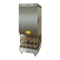
Identifies parts for the front view of the dispenser cabinet.

Dispenser Cabinet (rear view)

Identifies parts for the rear view of the dispenser cabinet.

Lower Back Panel

Identifies parts specific to the lower back panel.

Hopper Components

Lists and identifies the various components of the hoppers.

Temperature Probes and Hopper Supports

Identifies temperature probes and related hopper support parts.

Drum Motor Assembly

Lists and identifies parts for the drum motor assembly.

Basket Sensor Assembly

Lists and identifies parts for the basket sensor assembly.

Weighing System Assembly

Identifies components of the weighing system assembly.

Dispensing System Assembly (Models prior to s/n 28FR0802B0249)

Parts identification for the dispensing system (older models).

Dispensing System Assembly (Models after and including s/n 28F0802B0249)

Parts identification for the dispensing system (newer models).

Refrigeration System

General Operation

Describes the cold wall system and airflow requirements.

Required Maintenance

Details daily and monthly maintenance tasks for the refrigeration system.

Cleaning the Condenser Filter and Coil

Procedure for cleaning the condenser filter and coils.

Refrigeration System Components

Lists and identifies components of the refrigeration system.

Compressor Identification

Identifies domestic and international compressor models.

Refrigeration Specifications

Provides key specifications for the refrigeration system.

Compressor Start Component Wiring

Diagram showing wiring for compressor start components.

Condensing Unit Assembly

Identifies parts within the condensing unit assembly.

Electrical Diagram – Two Temperature Probe Configuration

Electrical Diagram – Single Temperature Probe Configuration