Revised 12/22/99 • LGE 5 © 1999 Automated Logic Corporation
• the Assigned Subnet Mask
• the Default Gateway Addr
4. Log out of SuperVision and set the IP Addr
DIPswitchtoAssigned.
5. Turn the LGE’s power on.
6. If using SuperVision v2.6, edit your HOSTS
file to include the following line for each
gateway (see TCP/IP Setup for SuperVision
for a detailed procedure):
IP Address LGx
Where IP Address is the address assigned
by the Network Administrator and x is the
gateway’s LGnet address.
7. If using SuperVision v2.6, run Setup.exe
on the disk shipped with your LGE.
This setup copies updated Portman files to
your emsys folder
8. Configure your connections page for
Network in SuperVision Plus v3.01 and
later, or NetBIOS in SuperVision v2.6.
Wiring
Power Wiring
The LGE has an operating range of 21.6VAC to
26.4VAC. If voltage measured at the module’s
power input terminals is outside this range,
the module may not work properly.
CAUTION The LGE module is a Class 2
device (less than 30VAC, 100VA maximum).
Take appropriate isolation measures when
mounting the LGE module in a control panel
where non-class 2 devices or wiring are
present.
You can power several modules from the
same transformer if you maintain the same
polarity.
1. Turn the module’s power off. This
prevents the module from being powered
up before the proper voltage is verified.
2. Make sure the 24VAC power source is off.
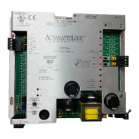
3. Connect the power wires to the module’s
power terminals labeled Ground and
24VAC (see Figure 1 for location).
4. Apply power to the transformer.
5. Make sure that 24VAC is present at the
module’spowerinputterminals.
6. Set the module’s LGnet address. Refer to
“Addressing” on page 3 for details about
setting the address.
7. Turn the LGE’s power switch on and verify
that the Run and Error LEDs are blinking.
Verify that the Error LED turns off and the
Run LED continues blinking (see Table 3
on page 8 to troubleshoot the LEDs).
Communications Wiring
When communicating at 156 kbps, the CMnet
uses a unique implementation of the industry
standard ARCNET protocol called ARC156.
For a summary of the differences between
ARCNET and ARC156, please refer to the
ARC156 CMnet Wiring Technical Instructions.
Use the appropriate wire for CMnet
communications. When communicating with
the ARC156 protocol, use an A3ARC156 wire
available from:
Magnum Cable Corporation
Cleveland, OH 44110-0500
(800) 421-0820
Use a dedicated 22AWG to 18 AWG twisted
pair (EIA-485) for legacy CMnet wiring. For
more information about CMnet wiring, refer
to the Technical Handbook or to ARC156
CMnet Wiring Technical Instructions.
Connecting to the CMnet
1. Turn off the power.
2. Connect the CMnet wires to the LGE’s
screw terminals as shown in Figure 4 on
page 6. Be sure to follow the same
 Loading...