Revised 8/14/02 • U551 11 © 2002 Automated Logic Corporation
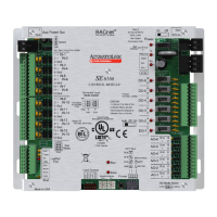
LEDs
The U551 modules have diagnostic LEDs to
assist troubleshooting.
Power - On when the module is on.
Rx - On when the module receives data.
Tx
-
On when the module transmits data.
DO1 - On when digital output 1 is active.
DO2 - On when digital output 2 is active.
DO3 - On when digital output 3 is active.
DO4 - On when digital output 4 is active.
DO5 - On when digital output 5 is active.
Production Date
To determine when a module was
manufactured, check the module status
report for the module in WebCTRL or
SuperVision. Refer to the appropriate user’s
guide for more information about the module
status report.
A sticker on the back of the module also
shows the date the module was
manufactured. The first three characters on
the sticker indicate the type of module. The
next two characters show the year and month
of manufacture. (The month digit is in
hexadecimal.)
Table 3. Inputs
I/O Type Signal Type
Channel
Number Range Offset Gain
IN-1
Thermistor 31
-17° to 213° F
-27° to 100.6° C
0.00
0.00
15.88
15.69
Volts 31 0 to 5V † †
Digital 21
IN-2
Thermistor 32
-17° to 213° F
-27° to 100.6° C
0.00
0.00
15.88
15.69
Volts 32 0 to 5V † †
Digital 22
Sw
Thermistor A3
-17° to 213° F
-27° to 100.6° C
0.00
0.00
15.88
15.69
Digital B3
LogiStat ‡
Temp
Thermistor
A1 or
A2‡‡
45° to 100° F
7.22° to 37.8° C
0.00
0.00
15.88
15.69
LogiStat ‡
Thermistor 33
-17° to 213° F
-27° to 100.6° C
0.00
0.00
15.88
15.69
IN-3 or
UDF 2
Volts 33 0 to 5V
Digital 23
UDF 2 Flow
(CFM)
‡‡‡
Flow
input
Flow (sensor
units)
‡‡‡
† Use the Point Help feature of SuperVision for Windows v2.0 or later to
determine offset and gain for these types of inputs.
‡ Channel numbers for these inputs are set by the LogiStat microblock and do
not need to be manually entered in SuperVision or Eikon.
‡‡ A1 is 10-second averaged. A2 is not averaged.
‡‡‡ Channel numbers for these inputs are set by the Airflow Control
microblock and do not need to be manually entered in SuperVision or Eikon.
Table 4. Analog Outputs
Point Signal Type
Channel
Number Range Offset Gain
AO 1 Analog 41 0 to 10VDC 0.00 0.0625
Table 5. Run LED
Status Meaning
2 times per second Normal operation.
5 times per second Transferring firmware.
Once every 2 seconds Auto-detecting baud rate.
Table 6. Error LED
Status Meaning
2 times per second Firmware error. Transfer
memory to the module to
correct.
Solid on Hardware failure.
 Loading...