p. 18/46
TLxx-MT-EN-04
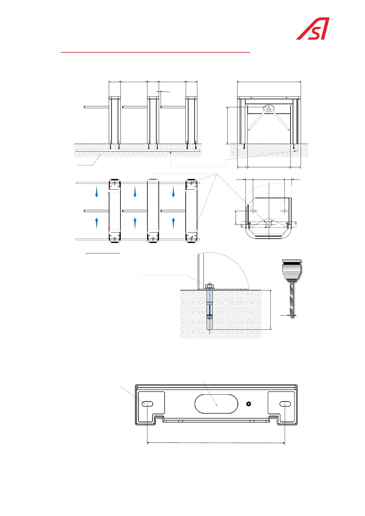
6.4. GENERAL DIMENSIONS AND INSTALLATION PLAN
With the TL2 housing, the power and data cables can be insert inside the housing through the right or left end box. But we
recommend a connection through the left (B) side considering that the main circuit breaker is located to the left.
min. 100*
AAA
BBB
Ø60
Ø15*
160 37.537.5
40
754
880 210210
80
Power supply and connection wiring inlet, can be through right or left end box
EXPANSIBLE ANCHOR B15/30
-/3413/000
(Suggested reference (M10))
Ø 60 mm PVC SHEATH.Concrete
Wiring to provide for:
230 V single phase power supply + ground, in 3G2.5 ²
IP CABLE (Ethernet) STP CAT.5
* Dimensions according to standard Automatic Systems anchoring.
Fig. 9- TL2 general dimensions and installation drawing ( plan CH9594)
340
Oblong hole
46 x 106 mm
for connecting
cables
Expansible anchor
M10
to provide
Fig. 10 Fixing points TL1 version