DL06 Micro PLC User Manual, 3rd Edition, Rev. E
5-232
Chapter 5: Standard RLL Instructions
1
2
3
4
5
6
7
8
9
10
11
12
13
14
A
B
C
D
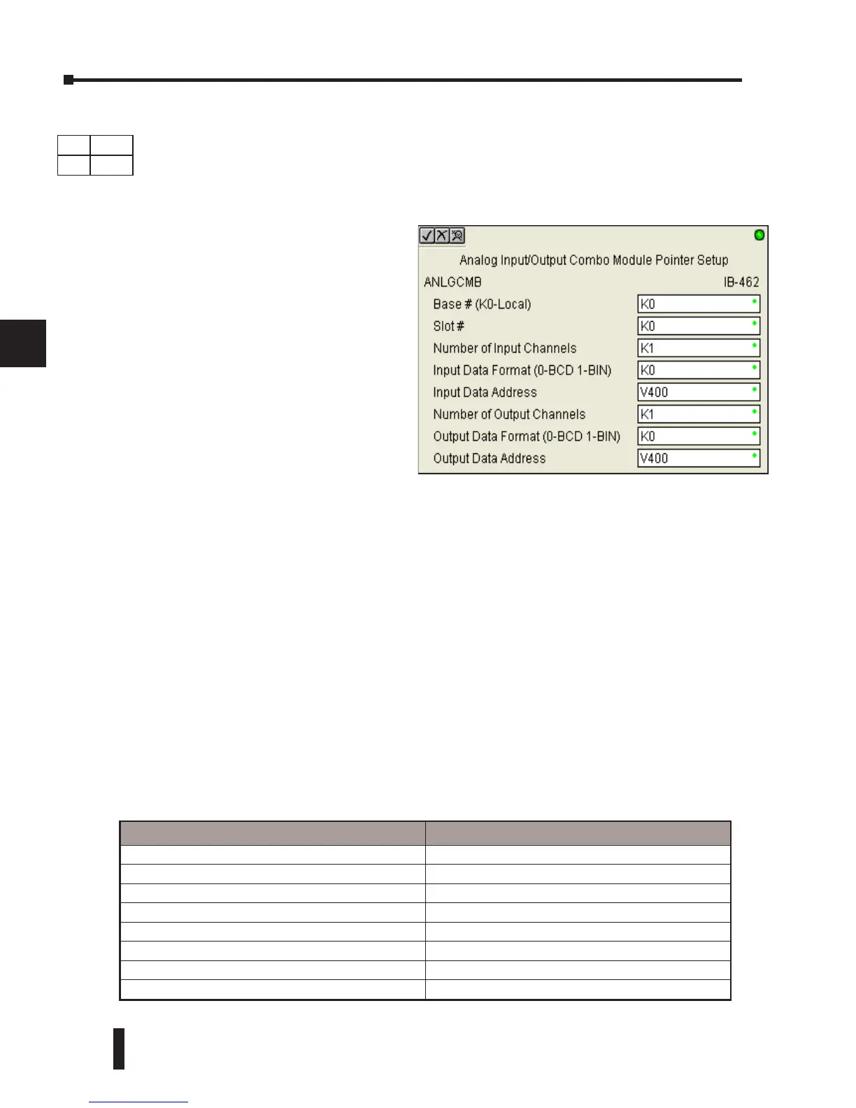
Analog Input/Output Combo Module Pointer Setup (ANLGCMB) (IB-462)
The Analog Input/Output Combo Module Pointer Setup instruction generates the logic to
configure the pointer method for an analog input/output combination module on the first
PLC scan following a Program to Run transition.
Since the IBox logic only executes on the first scan, the instruction cannot have any input logic.
ANLGCMB Parameters
• Base # (K0-Local): must be 0 for DL06 PLC
• Slot #: specifies which PLC option slot is occupied by the analog module (1–4)
• Number of Input Channels: specifies the number of analog input channels to scan
• Input Data Format (0-BCD 1-BIN): specifies the analog input data format (BCD or Binary) - the
binary format may be used for displaying data on some OI panels
• Input Data Address: specifies the starting V-memory location that will be used to store the analog
input data
• Number of Output Channels: specifies the number of analog output channels that will be used
• Output Data Format (0-BCD 1-BIN): specifies the format of the analog output data (BCD or
Binary)
• Output Data Address: specifies the starting V-memory location that will be used to source the analog
output data
DS Used
HPP
N/A
Parameter DL06 Range
Base # (K0-Local) K K0 (local base only)
Slot # K K1-4
Number of Input Channels K K1-8
Input Data Format (0-BCD 1-BIN) K BCD: K0; Binary: K1
Input Data Address V See DL06 V-memory map - Data Words
Number of Output Channels K K1-8
Output Data Format (0-BCD 1-BIN) K BCD: K0; Binary: K1
Output Data Address V See DL06 V-memory map - Data Words
The ANLGCMB IBox instruction
determines the data format and Pointer
addresses based on the CPU type, the
Base# and the module Slot#.
The Input Data Address is the starting
location in user V-memory where the
analog input data values will be stored,
one location for each input channel
enabled.
The Output Data Address is the starting
location in user V-memory where the
analog output data values will be placed
by ladder code or external device,
one location for each output channel
enabled


 To Next Page