GS1 Series AC Drive User Manual
5–9
Chapter 5: GS1 MODBUS Communications
DirectLOGIC MODBUS Ladder Programming
The set up for all of the DirectLOGIC CPUs is very similar. However, there may
be some subtle differences between CPUs. Refer to the appropriate CPU User
Manual for the specifics on your DirectLOGIC CPU.
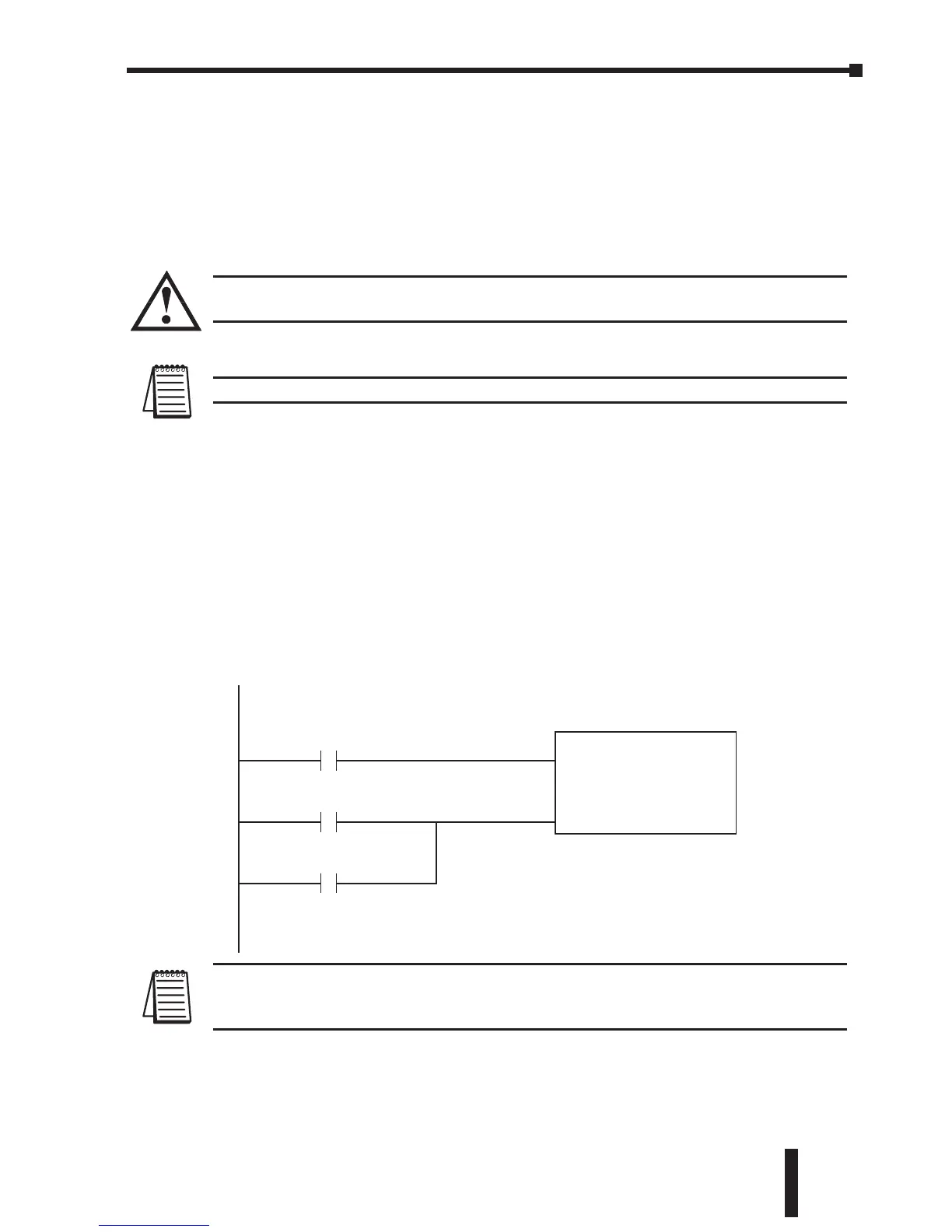
The following ladder program shows some examples of how to control the GS1
AC drive through MODBUS RTU. The drive should be setup and tested for
communications before it is connected to a load.
WARNING: A drive should never be connected to a load until any applicable
communication programs have been proven.
Note:This program is for illustration purposes only and not intended for a true application.
In many drive applications, electromagnetic interference can at times cause
frequent, short duration communication errors. Unless the application
environment is perfect, an occasional communication error will occur. In order to
distinguish between these non-fatal transients and a genuine communication
failure, you may want to use the instructions as shown in Rungs 1 through 4.
Rung 1 monitors the number of times that the PLC attempts to communicate with the
AC drive. When the PLC’s communication attempts are successful, SP116 will count
up and SP117 will not count. Once the count reaches 9999, the counter will reset
and resume counting.
Note: SP116 and SP117 are special relays in the DirectLOGIC CPUs that monitor the
PLC’s communications. SP116 is on when Port 2 is communicating with another device.
SP117 is on when Port 2 has encountered a communication error.
(Cont. next page)

 Loading...

