Setting Operation Mode
L: Light ON mode D: Dark ON mode
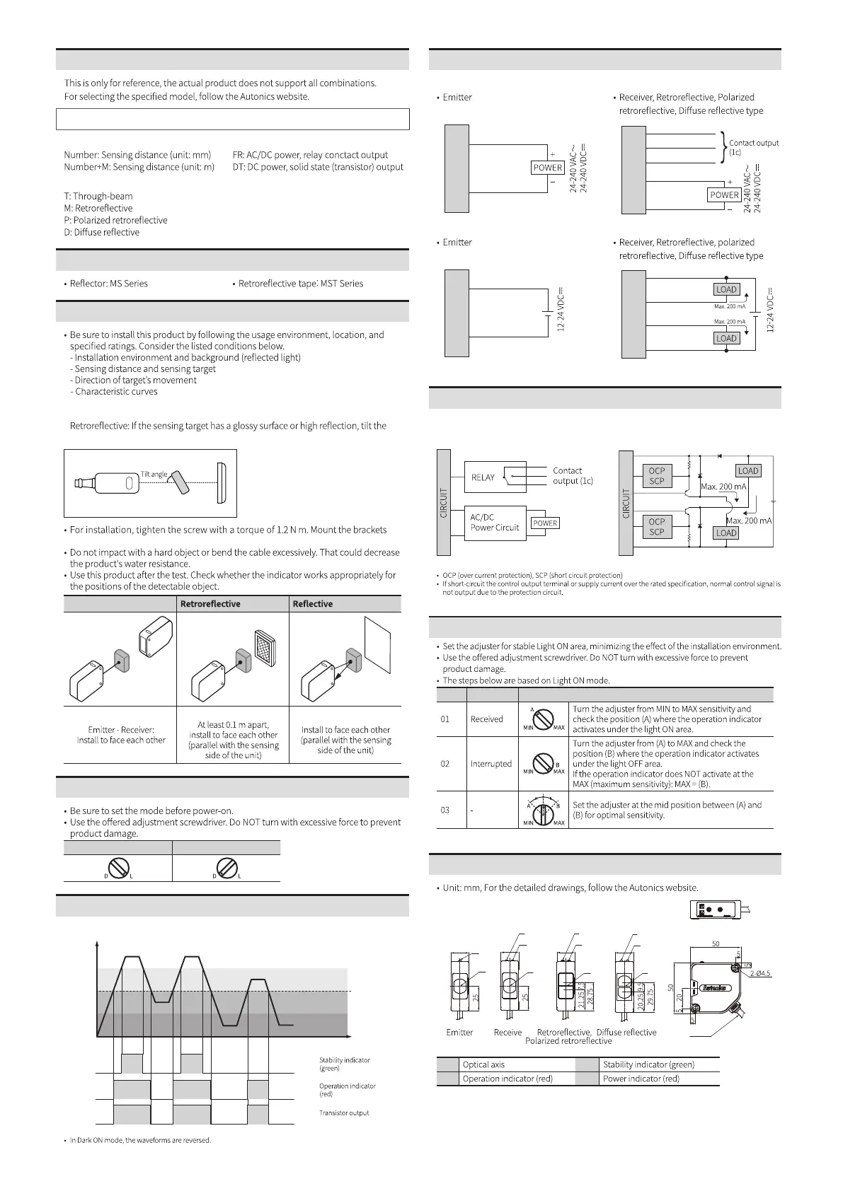
Cautions during Installation
Through-beam
Operation Timing Chart and Indicators
■ Light ON mode
ON
OFF
ON
OFF
ON
OFF
Received
light
Stable
light ON area
Unstable
light OFF area
Unstable
light ON area
Operation
level
Stable
light OFF area
Sold Separately
Ordering Information
BEN ❶ - ❷ ❸
❶ Sensing distance ❸ Output method
❷ Sensing type
• When installing multiple switch closely, it may result in malfunction due to mutual
interference.
•
sensing target with an angle from 30 to 45 degrees and install the switch.
Switch - Sensing target:
Switch - Reflector:
correctly to prevent the twisting of the switch's optical axis.
Sensitivity Adjustment
STEP Status Description
Dimensions
A
18
D
A
18
B
C
r
A
18
B
C
A
18
C
B
A C
B D
Circuit
■ AC/DC power, relay contact
output
■ DC power, solid state
(transistor) output
Connections
■ AC/DC power, relay conctact output
Brown
Blue
Black (Ta)
White (Tc)
Gray (Tb)
Brown
Blue
■ DC power, solid state (transistor) output
Brown
Blue
Brown
Black (NPN)
Blue
White (PNP)
Ø6, 2m
Ø5, 2m
 Loading...