Operation Timing Chart
ON
OFF
ON
OFF
ON
OFF
ON
OFF
Stable light ON area
Unstable light OFF area
Unstable light ON area
Stable light OFF area
ON Level
OFF Level
Received
light
Connections
Brown White
Blue Black
■ NPN open collector output ■ PNP open collector output
Brown
Brown
White
White
Black
Black
Blue
Blue
+
1
2
3
1
2
3
OCP
SCP
EmitterReceiver
CIRCUIT CIRCUIT
Brown
Brown
White
White
Black
Black
Blue
Blue
1
2
3
1
2
3
+
EmitterReceiver
CIRCUIT CIRCUIT
OCP
SCP
Cautions during Installation
Sold Separately
Product Components
Ordering Information
BW ❶ - ❷ ❸
❶ Optical axis pitch
❷ Number of optical axes
❸ Control output
Operation Indicator
◑
● OFF ◑◑ / ◑◑◑
Item
Emitter indicator Receiver indicator
Control
output
Power ON
MASTER operation
SLAVE operation
TEST input
Break of emitter
Break of emitting element
OFF
Installation
mode
OFF
OFF
OFF
Stable light ON
Unstable light ON
Unstable light OFF OFF
Stable light OFF OFF
Break of receiver OFF
Control output
over current
OFF
Malfunction of
Synchronous line
OFF
Failure of emitter (time out)
OFF
Optical axis
misalignment alarm
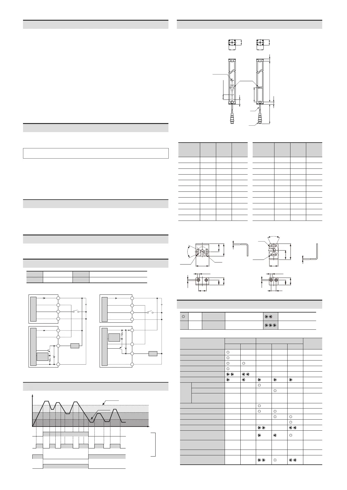
Dimensions
•
Emitter Receiver
60
B
A
10
L
10
300
■ Optical axis Pitch (A, B)
20 mm
■ Optical axis Pitch (A, B)
40 mm
Model
Product
length
(L)
Num. of
optical
axes
Sensing
height
160
12
320 16
20
560
32
36
Model
Product
length
(L)
Num. of
optical
axes
Sensing
height
160
6
320
10
12
560
16
20
22
■ Bracket A ■ Bracket B
16
2
25
16
10
15
50
2
32
10
10
15
 Loading...