A-129
SENSORS
CONTROLLERS
MOTION DEVICES
SOFTWARE
(A)
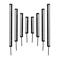
Photoelectric
Sensors
(B)
Fiber Optic
Sensors
(C)
LiDAR
(D)
Door/Area
Sensors
(E)
Vision
Sensors
(F)
Proximity
Sensors
(G)
Pressure
Sensors
(H)
Rotary
Encoders
(I)
Connectors/
Connector Cables/
Sensor Distribution
Boxes/ Sockets
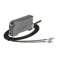
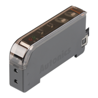
Color Mark Sensor
Feature
Outstanding color matching accuracy
- RGB light emitting diodes and 12-bit resolution
- 2 detection modes (color only / color + intensity)
- 3-step sensitivity adjustment for each mode (ne, normal, rough)
External light interference reduction minimizes errors and allows
stable detection
Check reference color with teaching indicator
Operation indicator (red LED), stability indicator (green LED),
timer indicator (orange LED)
Congure operation functions with external input from wiring
W1.24 × L6.7 mm spot size for detection of tiny targets and color marks
IP67 protection structure (IEC standard)
Overview
※
1: The weight includes packaging. The weight in parenthesis is for unit only.
※
The temperature and humidity of environment resistance is rated at non-freezing or condensation.
Model
BC15-LDT-C BC15-LDT-C-P
Sensing method Convergent reective type
Sensing distance 15mm ±2mm
Sensing target Opaque, translucent
Hysteresis Max. 20% of sensing distance (may vary by sensing mode or sensitivity)
Spot size 1.24×6.7mm (rectangular)
Response time 500
㎲
Power supply 12-24VDC ±10% (ripple P-P: max. 10%)
Current consumption Max. 30mA
Light source Full Color LED (red, green, blue)
Sensing mode C (color only) mode, C+I (color + intensity) mode
Output mode Color match output, color mismatch output
Output timer 40ms OFF delay timer function
Control output
NPN or PNP open collector output
• Load voltage: max. 30VDC • Load current: max. 100mA
• Residual voltage - NPN: max. 1VDC , PNP: max. 2.5VDC
Protection circuit Reverse polarity protection, output short overcurrent protection
Indicator Operation indicator: red LED, stability indicator: green LED, teaching indicator: full Color LED
Connection method Connector type
External input External SET cable input
Insulation resistance Over 20MΩ (at 500VDC megger)
Noise immunity ±240V of square wave noise (pulse width: 1
㎲
) from the noise simulator
Dielectric strength 1,000VAC at 50/60Hz for 1min
Vibration 1.5mm amplitude at 10 to 55Hz frequency in each X, Y, Z direction for 2 hours
Shock 500m/s² (approx. 50G) in each X, Y, Z direction for 3 times
Environ-
ment
Ambient illumination Incandescent lamp: max. 3,000lx (receiver illumination)
Ambient temp. -10 to 55
℃
, storage: -25 to 75
℃
Ambient humidity 35 to 85%RH, storage: 35 to 85%RH
Protection structure IP67 (IEC standard)
Material
Case: polycarbonate, sensing part: acrylic, bracket: stainless steel 304, bolt: carbon steel
Accessories Fixing bracket, M3 bolts: 2, adjustment screwdriver: 1
Approval
Weight
※
1
Approx. 80g (approx. 14g)
Specications
Applications
Packaging, stickers industry: Label status, Mark color check, etc.
Electronic components, semiconductor industry: Defective unit check, Connector color check, etc.
General photoelectric sensor detects present or absent of target by light.
Color mark sensor detects colors of surfaces by RGB (red, green, and
blue) light source.
Saving the desired color at the inner memory, color mark sensor emits
RGB LED light source to the target sequentially.
Color mark sensor calculates ratio of the three colors, RGB, for the
optimized sensing via the inner light collection lens.
Using o-axis optical system for minimized optical loss, and cylindrical
lens, BC Series compares setting color and sensing color with full-color
determination.
Red
Green
Blue
Red
Green
Blue
Please read “Safety Considerations”
in the instruction manual before using.
BC Series