B-33
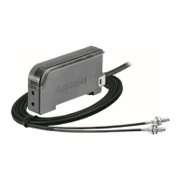
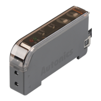
Fiber Optic Amplier
(A)
Photoelectric
Sensors
(B)
Fiber
Optic
Sensors
(C)
Door/Area
Sensors
(D)
Proximity
Sensors
(E)
Pressure
Sensors
(F)
Rotary
Encoders
(G)
Connectors/
Connector Cables/
Sensor Distribution
Boxes/ Sockets
(H)
Temperature
Controllers
(I)
SSRs / Power
Controllers
(J)
Counters
(K)
Timers
(L)
Panel
Meters
(M)
Tacho /
Speed / Pulse
Meters
(N)
Display
Units
(O)
Sensor
Controllers
(P)
Switching
Mode Power
Supplies
(Q)
Stepper Motors
& Drivers
& Controllers
(R)
Graphic/
Logic
Panels
(S)
Field
Network
Devices
(T)
Software
Features
High Reliability Of Fiber Optic Amplifier For Convenient Mounting
● High speed response: max. 0.5ms
● Auto sensitivity setting (button setting)/external input sensitivity setting type
● External synchronization input, mutual interference protection, self-diagnosis
● Reverse power polarity and short-circuit (overcurrent) protection circuit
● Timer function: selectable none / 40ms OFF delay timer (xed)
(standard type, remote sensitivity setting type only)
● Automatically selectable Light ON / Dark ON
● Precise detection of small target and easy to install in the complicated place
※
1: The weight includes packaging. The weight in parenthesis is for unit only.
※
The temperature or humidity mentioned in Environment indicates a non freezing or condensation environment.
Model
Standard type
External synchronization
input type
External input sensitivity
setting type
BF4RP BF4GP BF4R BF4G BF4R-E BF4G-E BF4R-R BF4G-R
Light source
Red LED
(660nm)
Green LED
(525nm)
Red LED
(660nm)
Green LED
(525nm)
Red LED
(660nm)
Green LED
(525nm)
Red LED
(660nm)
Green LED
(525nm)
Power supply 12-24VDC
ᜡ
±10% (ripple P-P: max.10%)
Current consumption Max. 45mA
Operation mode Light ON/Dark ON switching
Control output
NPN or PNP open collector output
● Load voltage: max. 30VDC
ᜡ
● Load current: max. 100mA
● Residual voltage - NPN: max. 1V (load current: 100mA), max. 0.4V (load current: 16mA) / PNP: max. 2.5V
Protection circuit Reverse polarity protection circuit, short-circuit (overcurrent) protection circuit
Response time Max. 0.5ms (frequency 1), max. 0.7ms (frequency 2)
Sensitivity setting Sensitivity setting button (ON/OFF)
Indicator
Control output indicator (OUT): red LED,
Stability indicator (STAB): green LED (turns ON at stable light ON/OFF level)
Mutual interference prevention Built-in differential frequency mode (frequency 1 (normal mode): max. 0.5ms, frequency 2: max. 0.7ms)
Self-diagnosis output
ON state under unstable sensing (when the target stays for 300ms in unstable level),
ON state when control output is short-circuited
● Load voltage: max. 30VDC
ᜡ
● Load current: max. 50mA
● Residual voltage - NPN: max. 1V (load current: 50mA), max. 0.4V (load current: 16mA) / PNP: max. 2.5V
Input of stop transmission function
-
Built-in
-
External synchronization function
-
Built-in (gate/trigger)
-
Remote sensitivity setting function
- -
Built-in
Timer function OFF delay (40ms)
-
OFF delay (40ms)
Insulation resistance Over 20MΩ (at 500VDC megger)
Noise immunity ±240V the square wave noise (pulse width: 1
㎲
) by the noise simulator
Dielectric strength 1,000VAC 50/60Hz for 1 minute
Vibration 1.5mm amplitude at frequency of 10 to 55Hz (for 1 min) in each X, Y, Z direction for 2 hours
Shock 500m/s² (approx. 50G) in each X, Y, Z direction for 3 times
Environ-
ment
Ambient illumination Sunlight: max. 11000
㏓
, Incandescent lamp: max. 3000
㏓
(received illumination)
Ambient temperature -10 to 50
℃,
storage: -20 to 70
℃
Ambient humidity 35 to 85% RH, storage:35 to 85% RH
Material Case: heat-resistance acrylonitrile butadiene styrene, cover: polycarbonate
Cable
Ø4mm, 4-wire, 2m
(AWG22, core diameter: 0.08mm, number of cores:
60, insulator out diameter: Ø1.25mm)
Ø4mm, 6-wire, 2m
(AWG24, core diameter: 0.08mm, number of cores:
40, insulator out diameter: Ø1mm)
Accessory Mounting bracket, bolts, nuts
Approval
Weight
※
1
Approx. 120g (approx. 65g)
Specifications
Please read “Safety Considerations” in operation
manual before using.
BF4 Series
BF 4 R P E-
No mark Standard type
E External synchronization input type
R External input sensitivity setting type
No mark NPN open collector output
P PNP open collector output
R Red LED
G Green LED
4 Series
BF Fiber Sensor
Ordering Information