A-131
Color Mark Sensor
SENSORS
CONTROLLERS
MOTION DEVICES
SOFTWARE
(A)
Photoelectric
Sensors
(B)
Fiber Optic
Sensors
(C)
LiDAR
(D)
Door/Area
Sensors
(E)
Vision
Sensors
(F)
Proximity
Sensors
(G)
Pressure
Sensors
(H)
Rotary
Encoders
(I)
Connectors/
Connector Cables/
Sensor Distribution
Boxes/ Sockets
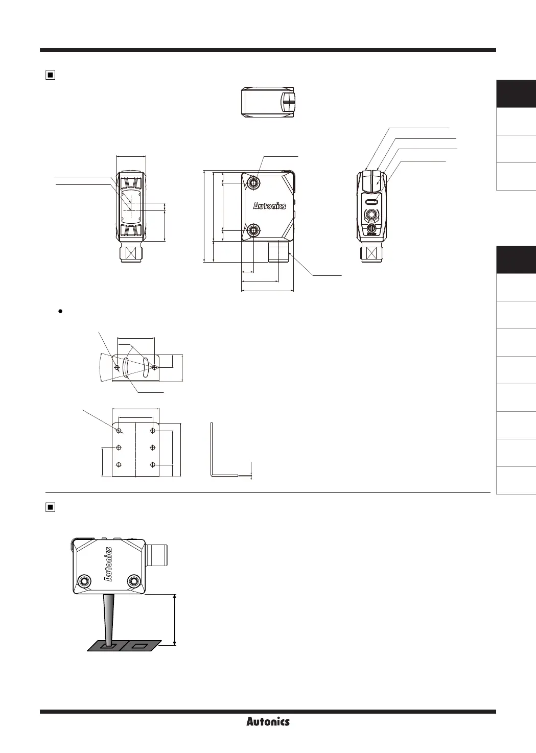
Dimensions
Fixing Bracket
(unit: mm)
①
Installation
: Place the color mark sensor and the target object facing each other then affix the
unit. The installation distance should be within ±2mm of 15mm .
②
Press the SET key to enter teaching standby status. Place the desired color at the
sensing position (spot) and hold the SET key for 3 seconds to set the reference
color. When it is complete, the teaching indicator will display the set color
③
Hold the SET key for 3 seconds change sensing mode and sensitivity settings.
④
Hold the SET key for 5 seconds to set the timer. The timer is a 40ms OFF delay
timer.
※
In case of teaching error, the output indicator and teaching indicator will flash
depending on the intensity of received light.
※
When detecting metal or glossy objects tilt install the sensor at about 10 to 20
degree angle.
※
When using photoelectric sensors closely over two units, it may result in malfunction
due to mutual interference.
※
When installing the product, tighten the screw with a tightening torque of 0.8N
.
m.
Within
15±2mm
Installation and Sensitivity Adjustment
11.2
16
M12 Tap
49.2
6.5
19.8
5.8
25.4
5.8
2-M3 Tap
16.5 4
37
28
9.4
2-Ø3.2
R22
30°
28
35
8.8
6-Ø3.2
40
1.2
20
4-R1.6
25.4
21.5
25.4
Optical axis of receiver
Optical axis of emitter
Operation indicator(red)
Stability indicator(green)
Timer indicator(orange)
Teaching indicator

 Loading...