A-130
BC Series
Connections for Connector Part
Operation Mode
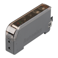
Unit Description
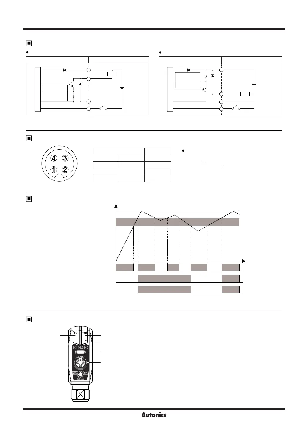
PNP open collector output
Connector cable (sold separately)
Control Output Diagram
NPN open collector output
Photoelectric sensor circuit Connection
Main circuit
(brown) +V
Load
(black) Output
(white) SET
(blue) 0V
12-24VDC
+
1
-
4
3
2
Output short
overcurrent
prevention
circuit
Photoelectric sensor circuit Connection
Main circuit
(brown) +V
(black) Output
(white) SET
(blue) 0V
12-24VDC
+
1
-
4
3
2
Output short
overcurrent
prevention
circuit
Load
Pin number Cable color Name
1 Brown +V
2 White SET
3 Blue GND (0V)
4 Black OUT
※
Connector cable model
: CIDH4-
(connector length : 2, 3, 5, 7m)
※
Please use Autonics M12 connectors.
For more information, please refer to the connector
cable section.
M12 Connector Pin
1. Operation indicator (OUT): ON (red) indicates operation.
2. Stability indicator (STB): ON (green) indicates stable status.
3. Timer indicator (TMR): ON (orange) when timer is set.
4. Teaching indicator:
Displays the reference color after successfully "teaching" the color.
※
The teaching color and the color displayed on the teaching indicator
may differ depending on environment conditions (ambient light,
reflection angle, material, etc.) .
5. SET key: Used for function settings.
6. Color match/mismatch switch
- N.O.: Output ON when target color matches reference color.
- N.C.: Output ON when target color does not match reference color.
1 2
3
4
5
6
※
The waveforms of “Operation indicator” and “Transistor output” are for color match mode operation.
They are opposite operation for color mismatch mode operation.
ON
OFF
ON
OFF
ON
OFF
Stability indicator (green LED)
Operation indicator (red LED)
Transistor output
Teaching value
Match rate
Sensitivity
Hysteresis
※
If short-circuit the control output terminal or supply current over the rated specification, normal control signal is not output due to the output
short over current protection circuit.

 Loading...