Do you have a question about the Autonics KN-2000W Series and is the answer not in the manual?
Covers essential safety guidelines, warnings, and cautions for safe operation and hazard avoidance.
Highlights the main features and capabilities of the 1-Channel Digital Temperature Indicators.
Provides important precautions and guidelines to prevent unexpected accidents during the unit's operation.
Lists included physical components and information on the DAQMaster software.
Details input types, operating ranges, and display accuracy specifications.
Provides technical specifications for the RS485 communication interface, including protocol and speed.
Provides physical dimensions, panel cut-out requirements, and electrical connection diagrams.
Details error displays and their corresponding troubleshooting steps for diagnosing issues.
Guides users through setting operational modes and configuring unit parameters.
Configure input type, temperature unit, and display unit for accurate measurement and display.
Set up alarm operations, hysteresis, options, and transmission output parameters.
Customize display colors, set communication address, speed, and write parameters.
Instructions for reading input status and registers via the communication interface.
Settings for monitoring specific parameters like alarm temperatures and peak values.
Details input specification mapping, special functions (root, square), and digital filtering for signal processing.
Explains how to set and display high/low limit values for measured inputs.
Details alarm operation modes (absolute, sensor break) and option settings (latch, standby).
Provides a table explaining the meaning of various segments displayed on the unit.
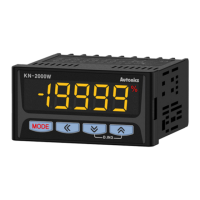
The Autonics KN-2000W Series is a 1-channel digital temperature indicator designed for precise measurement and display of various temperature and analog signals. This device offers high accuracy and a broad display range, making it suitable for a wide array of industrial applications.
The core function of the KN-2000W is to accurately measure and display temperature or analog input signals. It supports a diverse range of input types, including 12 types of thermocouples, 5 types of RTDs, and 8 types of analog inputs (2 current types and 6 voltage types). This versatility allows it to integrate into numerous systems without requiring multiple specialized devices. The device features a 16-bit Analog-to-Digital Converter (ADC), ensuring high measurement accuracy.
A key functional aspect is its auto display color change feature. This allows the indicator's display color to automatically change when an error occurs or an alarm is triggered, providing immediate visual feedback to operators. This enhances safety and operational awareness, allowing for quick identification of abnormal conditions.
The KN-2000W also incorporates various output options to facilitate integration into control systems. It offers alarm outputs with either 2 or 4 points, enabling the device to trigger external actions based on predefined thresholds. Additionally, it provides an isolated 4-20 mA transmission output, which can be used to send the measured process value (PV) to other control devices or data acquisition systems. For communication with supervisory systems, the device includes an RS485 communication output, supporting the Modbus RTU protocol. This allows for remote monitoring and parameter setting, enhancing system flexibility and control.
Several built-in functions further expand its utility. It supports high/low peak input monitoring, which is useful for tracking maximum and minimum values over time. Alarm outputs can be configured for upper/lower limits or sensor break conditions, providing critical alerts for process deviations or sensor failures. The transmission output and display scale can be adjusted to match specific application requirements. A digital input (DI) function is also available, allowing for external control or triggering of specific device actions. Furthermore, the device includes a built-in 24 VDC power supply for sensors or transmitters, simplifying wiring and reducing the need for external power sources.
For analog inputs, the device offers special functions to display calculated actual values. These include linear, root, and square functions, which are particularly useful for applications involving flow measurement by pressure signals or outputting differential pressure. A "Two Unit Function" is also available, allowing the display of pressure under atmospheric conditions in mmHg.
The device also features an input digital filter, which employs a moving average algorithm to stabilize the display and output by filtering out noise from input lines and irregular signals. This ensures a more reliable and consistent measurement, especially in noisy industrial environments.
The KN-2000W is designed for ease of use and integration. It is intended for panel mounting, ensuring a secure and organized installation within control panels. The front panel features a clear 7-segment LED display, available in red, green, and yellow, which provides excellent visibility of the measured values and parameters. The display range from -19999 to 19999 accommodates a wide variety of measurement scales.
Navigation and parameter setting are intuitive, utilizing a combination of [MODE], [▲], [▼], and [✔] keys. The [MODE] key allows users to enter parameter set mode, move between parameters, save settings, and return to run mode. The [▲] and [▼] keys are used to change setting values, while the [✔] key is used to select parameters or move between digits during setting. This user-friendly interface simplifies configuration and adjustment.
The device supports both AC (100-240 VAC~) and DC (24 VDC=) power supply options, offering flexibility in power integration. It is designed to operate within a permissible voltage range of 90% to 110% of the rated voltage, ensuring stable performance.
For communication, the RS485 interface supports Modbus 1.1 RTU protocol, allowing connection of up to 32 units in an asynchronous, two-wire half-duplex method. The communication speed is configurable, with options ranging from 1,200 to 19,200 bps, enabling integration into various network architectures. The effective communication range is up to 1,200 meters, or 700 meters recommended, providing ample distance for distributed control systems.
The device's alarm functions are highly configurable. Alarm operations can be set as absolute high limit, absolute low limit, or sensor break alarms. Alarm options include standard alarm, alarm latch, standby sequence, and a combination of alarm latch and standby sequence, providing flexible control over alarm behavior. The alarm output hysteresis is also adjustable, preventing rapid toggling of alarm states due to minor fluctuations around the setpoint.
Maintenance of the KN-2000W Series is straightforward, focusing on ensuring continuous and reliable operation. The device is built with robust components, including relays with high mechanical and electrical life cycles, contributing to its longevity.
For cleaning, it is recommended to use a dry cloth. The manual explicitly warns against using water or organic solvents, which could damage the unit or cause electric shock. This simple cleaning instruction helps preserve the device's integrity.
The design emphasizes protection against common industrial hazards. Users are advised to keep the product away from metal chips, dust, and wire residue, which could flow into the unit and cause damage or malfunction. This highlights the importance of maintaining a clean installation environment.
The device incorporates error displays to aid in troubleshooting. For instance, "bUrN" indicates a disconnected or unconnected input sensor, "HHHH" or "LLLL" signifies that the process value (PV) is outside the input range, and "Err" or "Err1" points to setting value errors or inconsistencies in input specification settings. These error codes provide immediate diagnostic information, allowing operators to quickly identify and address issues.
The memory retention feature ensures that settings are preserved for approximately 10 years, even without power, thanks to non-volatile semiconductor memory. This reduces the need for frequent re-configuration after power outages or during maintenance.
For installation, the manual specifies that the unit should be installed on a device panel and recommends using crimp terminals for power connections to ensure secure and reliable wiring. It also advises installing a power switch or circuit breaker in an easily accessible location for quick power disconnection, enhancing safety during maintenance.
To minimize inductive noise, it is recommended to keep the device away from high voltage lines and power lines and to avoid using it near equipment that generates strong magnetic forces or high-frequency noise. Using twisted pair wire for communication lines is also suggested to improve signal integrity. These recommendations contribute to the device's long-term stability and accurate performance in industrial environments.
| Model | KN-2000W Series |
|---|---|
| Category | Measuring Instruments |
| Mounting | Panel mount |
| Humidity | 35 to 85%RH (non-condensing) |
| Display | LED |
| Digits | 4 |
| Output | Relay, Current |
| Accuracy | ±0.3% FS |
| Communication | RS-485 |
| Operating Temperature | 0 to 50°C |
| Storage Temperature | -20 to 60°C |