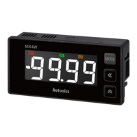
EasyManua.ls Logo

Autonics MX4W Series User Manual

Autonics MX4W Series
6 pages
To Next Page IconTo Next Page
Page #1 background imageLoading...
Page #1 background image
-|Transparent Guide|-
Features
LCD display with easy-to-read white PV characters
Isolated input and power modules allow powering of multiple units using a single
power supply
Compact, space-saving design (rear-length: 20 mm)
: reduced rear-length size by 80 % compared to same DIN size panel meters (MT4W)
Various input options (by model)
- Input options: DC / AC voltage, DC / AC current

Display range: -9999 to 9999
High / low-limit display scale function
AC frequency measurement (range: 0.100 to 1200 Hz)
Preset output: OUT1, OUT2 (NPN / PNP open collector output)
Power factor display / output function
: displays analog outputs (1 - 5 V, 4 - 20 mA) from power factor converters as -0.50 to
1.00 to 0.50
Various functions
: peak display value monitoring, display cycle delay, zero-point adjustment, peak
display value correction, etc.


TCD210071AA
LCD Multi Panel Meters
MX4W Series
PRODUCT MANUAL
For your safety, read and follow the considerations written in the instruction
manual, other manuals and Autonics website.
󹃑
improvement. Some models may be discontinued without notice.
Safety Considerations
Observe all ‘Safety Considerations’ for safe and proper operation to avoid hazards.


Failure to follow instructions may result in serious injury or death.
01. 



󹃑
02. 󹃓


󹃑
03. 
󹃑
04. 
󹃑
05. 
󹃑
06. Do not disassemble or modify the unit.
󹃑

Failure to follow instructions may result in injury or product damage.
01. 
AWG 24 (0.20 mm
2

2


󹃑
failure.
02. 󹃒
󹃑
03. 
󹃑
04. 󹃓
into the unit.
󹃑

Follow instructions in ‘Cautions during Use’.
Otherwise, It may cause unexpected accidents.
Power supply should be insulated and limited voltage / current or Class 2, SELV power
supply device.
Install a power switch or circuit breaker in the easily accessible place for supplying or
disconnecting the power.
Keep away from high voltage lines or power lines to prevent inductive noise.
󹃑
power line and shielded wire at input signal line.
Do not use near the equipment which generates strong magnetic force or high
frequency noise.
󹃒 Connection with the varistor
󹮭󹮭󹮭
󹮭󹮭󹮭󹮭

󹮭
HI
LOW
󹮭
HI
LOW
󹮭

This unit may be used in the following environments.
󹃑
- Altitude max. 2,000 m
- Pollution degree 2
- Installation category II
Question and Answer IconNeed help?

Do you have a question about the Autonics MX4W Series and is the answer not in the manual?

Autonics MX4W Series Specifications

General IconGeneral
ModelMX4W Series
CategoryMeasuring Instruments
Display Digits4
Input TypeResistance
Power Supply24V AC 50/60 Hz
Control OutputRelay
Auxiliary OutputVoltage, Current
CommunicationRS-485
Operating Temperature0°C to 50°C (32°F to 122°F)
Storage Temperature-20°C to 60°C (-4°F to 140°F)

Summary

Safety Considerations

Warning: Critical Safety Instructions

Critical safety instructions for preventing serious injury or death due to improper use.

Caution: Potential Hazards

Precautions to prevent potential injury or product damage from specific conditions or actions.

Cautions during Use

Operational and Installation Guidelines

Guidelines for safe installation, power supply, and preventing inductive noise.

Product Features

Key Features Overview

Highlights key features such as LCD display, compact design, and versatile input/output options.

Ordering Information

Model Selection Guide

Information on how to select a model based on input type and output options.

Connections

Wiring and Terminal Guide

Illustrates wiring and terminal connections for input, output, and power.

Product Components

Included Accessories

Lists the items included with the product, such as brackets and manuals.

Dimensions

Physical and Panel Dimensions

Provides physical dimensions and panel cutout specifications for installation.

Cautions during Wiring

Wiring Best Practices

Guidelines for proper wiring, emphasizing insulation and terminal usage.

Specifications

Technical Specifications Summary

Comprehensive technical details including input type, display, accuracy, power, and environmental ratings.

Mode Setting

Navigating Setting Modes

Explains the procedure for entering and navigating through different setting modes.

Parameter Setting

Parameter Configuration Details

Details the configuration of various parameter groups (1, 2, and 0) for device settings.

Input Range and Display Range

Input Range to Display Mapping

Maps input ranges for voltage and current to corresponding display ranges and methods.

Output Operation Mode

Configuring Output Operations

Explains the different output operation modes (OFF, HI, LOW, HL) for OUT1 and OUT2.

Power Factor Display

Power Factor Measurement and Display

Details how to display power factor (cosØ) using analog output signals from transducers.

Error Handling

Error Codes and Troubleshooting

Lists error codes, their causes, and basic troubleshooting steps.

Reset Procedure

Factory Reset Instructions

Provides instructions for resetting all parameters to factory default settings.

Detailed Function Descriptions

Frequency Measurement and Display Adjustments

Covers frequency measurement, display gradient, limit settings, and zero point adjustment.

Error and Timing Management

Display Error Correction and Startup Time

Explains display error correction methods and startup compensation time for stable operation.

Display Cycle and Peak Value Monitoring

Details managing display fluctuations and monitoring maximum/minimum peak values.

Display Segment Reference

Segment Table Interpretation

Explains the meaning of different segments displayed on the product screen.

Related product manuals