Error
Error display is released automatically when it is in the measured and display range.
HHHH
Disconnect power supply
and check the cables.
LLLL
D-HH
Reset within the display
range.
D-LL
F-HH
-PF-H
PF-L
OVER
Reset within the zero range.
Reset
01.
alternately for 0.5 sec in turn.
02.
03.
to run mode.
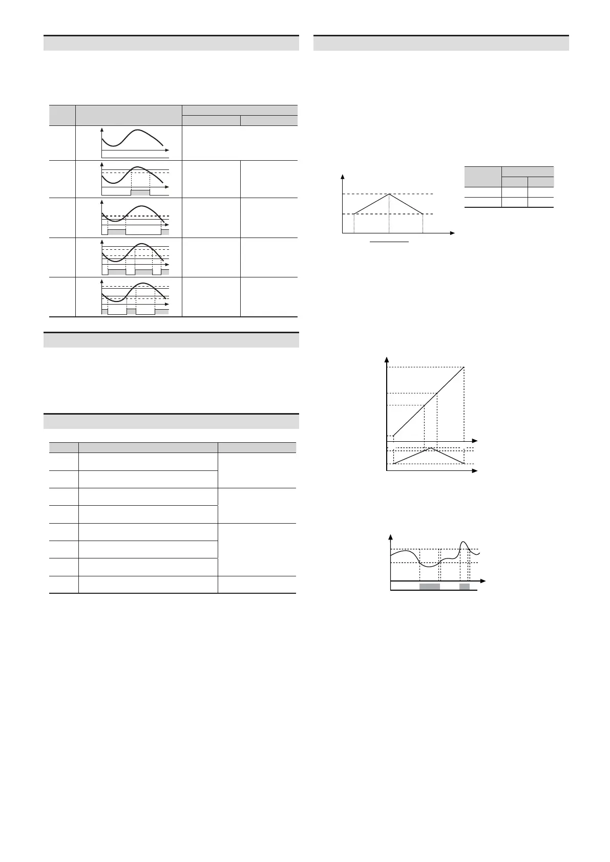
• The below describes based on OUT1.
• OUT1 and OUT2of output operations are same. It operates individually by the set output
operation mode.
• When changing output operation mode,
are reset.
MODE
OFF
OFF
OUT
output
HIGH
Hys
OUT
LOW
Hys
OUT
HL
Hys
OUT
HL-G
Hys
OUT
•
•
transducer.
- LEAD: current phase leads voltage phase
• It is available to accept several outputs of the power factor transducer by high / low-
limit input value analog output value setting in the power factor transducer.
•
• Setting range: from min. to max. selected value from input range
• E.g.: When setting 200V in input range, high / low-limit input value are available to set from
-200.0 to 200.0. When setting 20V, high / low-limit input value are available to set from
-20.00 to 20.00.
value
cosØ
value
1
0.5
LEAD
2
Default
H-RG L-RG
500.0 000.0
5.000 0.000
• E.g. 1: When the output of the power factor transducer is DC 4 - 20 mA
1. Connect the output to the input terminal 7 (+), 8 (-) of this unit, then set input range as 4-20.
2. When setting the input range as 4-20, low-limit input value is set as 4.00 and high-limit input
value is set as 20.00 automatically.
20 mA, it displays 0.50.
1-5B.
2. Set high-limit input value as 5.00 and low-limit input value as 1.00 for the output of the
power factor transducer.
V, it displays 0.50.
1V
5V
0.50
0.75
0.90
1.00
-0.90
-0.75
-0.50
Low
1
0.9
0.5
LEAD
•
1. Set OUT1 output operation mode as HL at parameter 2 group.
2. Set OUT1 high-limit output setting value as 0.90 and OUT1 low-limit output setting value as
-0.90 at parameter 0 group.
LEAD
Hys
0.90
HL
OUT1 high-limit
output setting value
1.00
-0.90
Hys
 Loading...