EasyManua.ls Logo

Autonics MT4W Series User Manual

Autonics MT4W Series
6 pages
To Next Page IconTo Next Page
Page #1 background imageLoading...
Page #1 background image
-|Transparent Guide|-
TCD220015AA
4-Digit Multi Panel Meters
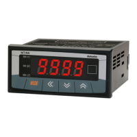
MT4W Series
PRODUCT MANUAL
For your safety, read and follow the considerations written in the instruction
manual, other manuals and Autonics website.
󹃑


Features















Safety Considerations




01. 



󹃑
02. 󹃓


󹃑
03. 
󹃑
04. 
󹃑
05. 
󹃑
06. Do not disassemble or modify the unit.
󹃑


01. 
AWG 24 (0.20 mm
2

2



󹃑

02. 󹃒
󹃑
03. 
󹃑
04. 󹃓
into the unit.
󹃑









󹃑



󹃒 Connection with the varistor
󹮭󹮭󹮭
󹮭󹮭󹮭󹮭

󹮭
HI
LOW
󹮭
HI
LOW
󹮭


󹃑



Question and Answer IconNeed help?

Do you have a question about the Autonics MT4W Series and is the answer not in the manual?

Autonics MT4W Series Specifications

General IconGeneral
Display TypeLED
Display Digits4 digits
Input TypeThermocouple, RTD, DC voltage, DC current
CommunicationRS-485 (Modbus RTU)
Mounting TypePanel Mount
Storage Temperature-20 to 60°C
Power Supply100-240 VAC 50/60Hz
Control OutputRelay
Operating Temperature-10 to 50 ℃
Accuracy±0.3% FS ±1 digit

Summary

Safety Considerations

General Warnings

Advisories regarding potential hazards, injury, or death from improper use or installation.

Usage Precautions

Guidelines for safe operation, installation, and maintenance to prevent accidents or damage.

Wiring and Connections

Cautions During Wiring

Recommendations for using appropriate wires and terminals for safe and reliable connections.

Input and Output Connections

Detailed diagrams and pinouts for connecting various input signals and output types.

Product Specifications

General Specifications

Key technical details including input limits, accuracy, display range, dimensions, and communication interface.

Environmental and Power Specs

Information on operating environment, vibration resistance, and power supply requirements.

Parameter Configuration

Parameter Group 2 Settings

Configuration options for output operations, display settings, and input signal handling.

Input Range and Display Range

Settings for input ranges and corresponding display resolutions for various measurement types.

Output Operation Modes

Output Operation Logic

Explanation of different output modes (H.SET, L.SET, etc.) and their behavior based on input values.

Time Chart and Error Handling

Visualizations of output signals and troubleshooting guide for common errors.

Function Descriptions

Display Method and Frequency Measurement

Details on display modes, including frequency measurement accuracy and requirements.

Scale Adjustment and Zero Point

Functions for adjusting display gradients, transmission output scales, and zero point calibration.

Error Correction and Startup Time

Methods for correcting display errors and managing startup compensation time.

Related product manuals