frequency
It measures input signal frequency when it is AC input.
In order to measure frequency normally, input signal, over 10 % F.S. of the rated input range,
should be supplied. Otherwise, it may not be measured normally.
The measurement range differs depending on the decimal point position.
It is available to adjust the high-limit display value gradient correction and exponent of SPAN at
parameter setting.
• Accuracy of frequency measurement: below 1 kHz: F.S. ± 0.1 % rdg ± 2-digit,
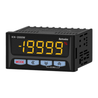
This function is to correct a gradient of high / low-limit scale value.
And also can be used as correction function of high-limit scale value.
Adjustment range is setting value and multiply current gradient.
5.000
20 50V
12.500
value
H-SC L-SC Result
12.500 0.000 1.000 Disable
0.000 2.000
0.000 4.000
2.500 0.000 5.000
value
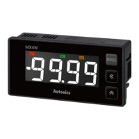
80.0 200.0
-400.0
400.0
0.0
-200.0 -80.0
H-SC L-SC Result
400.0 -400.0 1.000
-80 mA
200.0 -200.0 2.000
100.0 -100.0 4.000
80.0 -80.0 5.000
1.
correction at -200 mA must be -400.0. But it is disable due to setting range is 9.999.
•
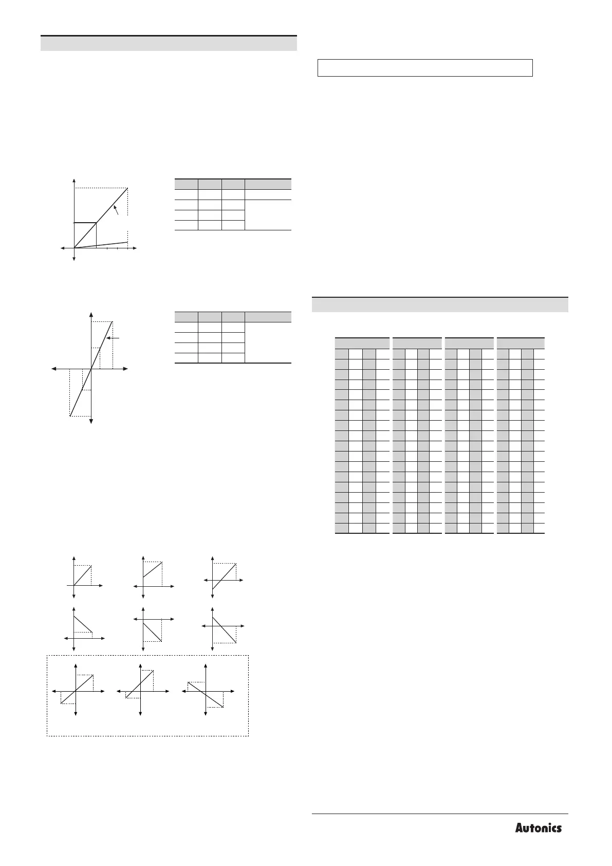
This function is to display setting of particular high / low-limit value in order to display high /
low-limit value of measured input.
below graphs.
• When changing input range, it is changed automatically as factory default display range of
the input range.
• In case of DC voltage / current input model and using minus input,
they are displayed.
Display
value
A
A
A
B
B
B
a a
a
b b b
Display
value
Display
value
Input
value
Input
value
Input
value
Display
value
Display
value
Display
value
Display
value
Display
value
Input
value
Input
value
Input
value
Input
value
Input
value
a
a
a
a
a
b
b
b
b
b
B
B
A
A
B
B
B
A
A
A
Display
value
Input
value
a b
B
A
Zero adjustment
1. low-limit display value deviation correction parameter.
2. P
0 0 I I 0 0 I I 0 0 I I 0 0 I I
1 1 J J 1 1 J J 1 1 J J 1 1 J J
2 2 K K 2 2 K K 2 2 K K 2 2 K K
3 L L 3 L L 3 L L 3 L L
4 4 M M 4 4 M M 4 4 M M 4 4 M M
5 5 N N 5 5 N N 5 5 N N 5 5 N N
6 O O 6 O O 6 O O 6 O O
7 7 P P 7 7 P P 7 7 P P 7 7 P P
8 8 Q Q 8 8 Q Q 8 8 Q Q 8 8 Q Q
9 9 R R 9 9 R R 9 9 R R 9 9 R R
A A S S A A S S A A S S A A S S
B B T T B B T T B B T T B B T T
C C U U C C U U C C U U C C U U
D D V V D D V V D D V V D D V V
E E W W E E W W E E W W E E W W
F F X F F X F F X F F X
G Y G Y G Y G Y
H H Z Z H H Z Z H H Z Z H H Z Z
Error correction
)
+ Low-limit display value deviation correction
The display value to 500 V measured input varies by adjusting the offset of low-limit
display value.
If this display value is 501.0, calculate 500.0 / 501.0 (desired display value / the display value),
and set the 0.998 correction value as the high-limit display value gradient correction parameter
to display 500.0 by adjusting gradient of high-limit value.
It monitors max./min. peak value of display value based on the current displays value and then
displays the data at the parameters. When pressing the front direction keys at the same time
for over 1 sec at the parameters, the monitored data is initialized.
Set the delay time at peak monitoring delay time parameter in order to prevent malfunction
caused by initial overcurrent or overvoltage, when monitoring the peak value.
 Loading...