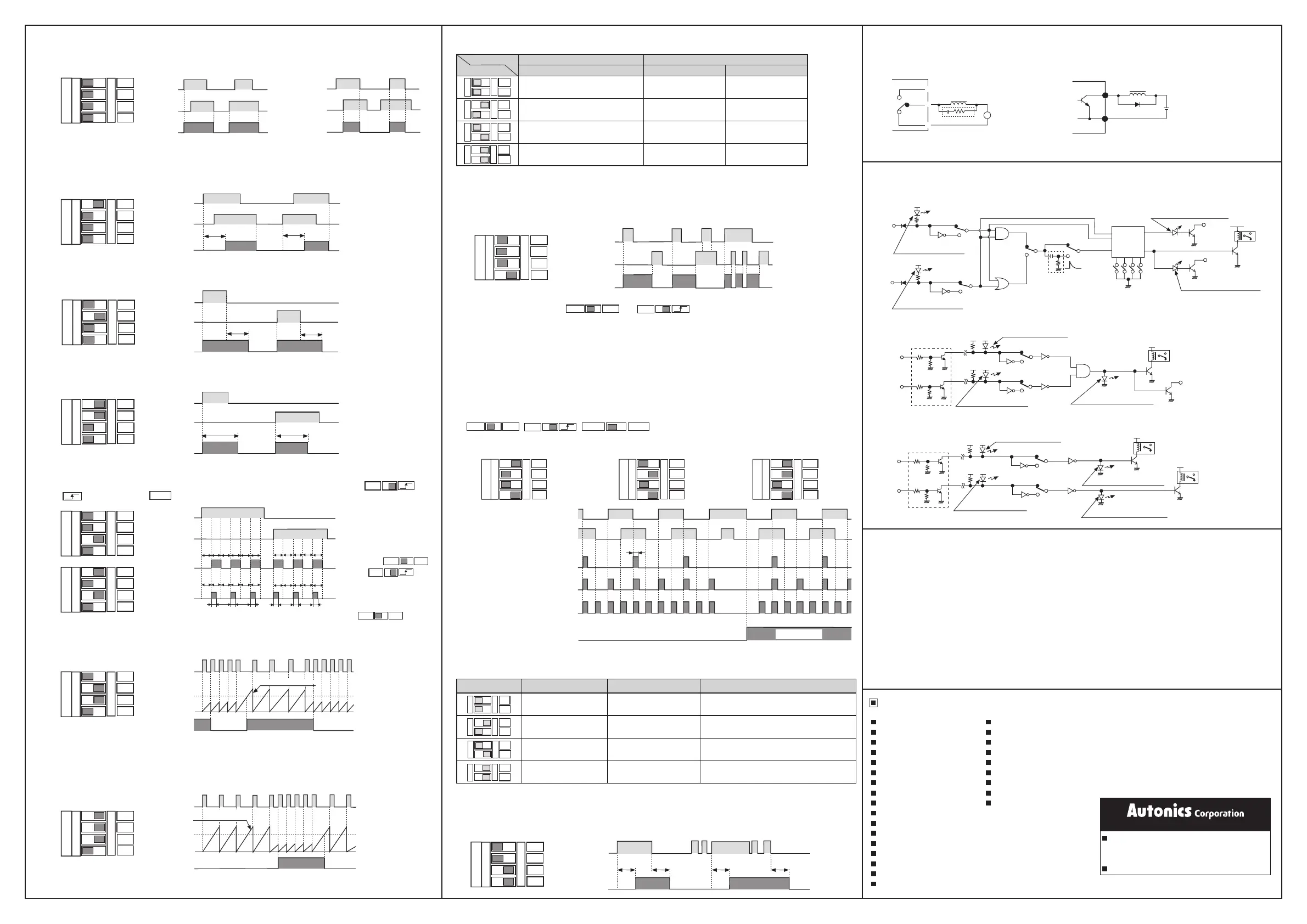
▣ Operation Mode
●
MODE 1 ON-DELAY MODE
: OUT will be ON after setting time when one of IN1 and IN2 is ON. When IN1 and IN2 are OFF,
OUT will be OFF. (This is when input logic is OR)
T: Setting time
SA
SB
SC
SD
O
N
M
O
D
E
O
F
F
ON
OFF
IN1
IN2
OUT
ON
OFF
ON
OFF
T
T
●
MODE 2 OFF-DELAY MODE
: OUT will be ON at the same time when IN1 or IN2 is ON then OUT will be OFF after setting time when
IN1 or IN2 is OFF. (This is when input logic is OR)
T: Setting time
SA
SB
SC
SD
O
N
M
O
D
E
O
F
F
ON
OFF
IN1
IN2
OUT
ON
OFF
ON
OFF
T
T
●
MODE 3 ONE-SHOT DELAY MODE
: OUT will be ON at the same time when IN1 or IN2 is ON then OUT will be OFF after setting time.
(This is when input logic is OR)
T: Setting time
SA
SB
SC
SD
O
N
M
O
D
E
O
F
F
ON
OFF
IN1
IN2
OUT
ON
OFF
ON
OFF
T
T
●
MODE 0 NORMAL MODE
: OUT will work according to input signal regardless Timer.
SA
SB
SC
SD
O
N
M
O
D
E
O
F
F
ON
OFF
ON
OFF
IN1 IN1
<OR function> <AND function>
IN2 IN2
OUT OUT
※Output will be ON when either
IN1 or IN2 is ON.
※Output will be ON when both
IN1 and IN2 are ON.
ON
OFF
ON
OFF
ON
OFF
ON
OFF
Note) In case of One-Shot
Mode, it is not diffe-
rent between
S/W se-
lections.
AND
OR
Note)ON/OFF rate of
Flicker output is 1:1.
Note) In case of Flicker Mode,
it is not different
between
and S/W.
AND
OR
NORM
●MODE 4,5 FLICKER MODE / FLICKER ONE-SHOT MODE
: OUT will be ON after setting time for IN1 input then it is ickering and OUT will be ickering after setting
time from ON and IN2 input is same. Incase One-shot Mode, output time(Ts) will be selected by S/W.
( : Ts= Approx. 10ms, : Ts= Approx. 100ms)
NORM
SA
SB
SC
SD
O
N
M
O
D
E
O
F
F
※T : Setting time, Ts : One-Shot output time
ON
OFF
IN1
IN2
T
T T T T T T T T T T T
Ts Ts Ts Ts Ts Ts
T T T T T T T T T T
MODE 4
OUT
MODE 5
OUT
ON
OFF
ON
OFF
ON
OFF
SA
SB
SC
SD
O
N
M
O
D
E
O
F
F
TIME S/W Max. input frequency Output pulse width(Tw)
Input speed of connected equipment(cps)
100kHz Approx. 0.5㎲ Min. 2000kHz(2,000kcps)
10kHz Approx. 5㎲ Min. 200kHz(200kcps)
1kHz Approx. 50㎲ Min. 20kHz(20kcps)
100Hz
Approx. 500㎲ Min. 2kHz(2kcps)
T1
T2
O
N
O
F
F
T1
T2
O
N
O
F
F
T1
T2
O
N
O
F
F
T1
T2
O
N
O
F
F
◎TIME S/W function in Encoder mode
: TIME S/W is to convert output pulse width(Tw).
MODE 1 to MODE 7, MODE 12
MODE 6 to MODE 7
Setting time range Input frequency rpm
0.01 to 0.1sec 100 to 10Hz 6,000 to 600rpm
0.1 to 1sec 10 to 1Hz 600 to 60rpm
1 to 10sec 1 to 0.1Hz 60 to 6rpm
10 to 100sec 0.1 to 0.01Hz 6 to 0.6rpm
◎TIME S/W function(MODE 1 to MODE 7)
: Set the setting time by TIME S/W(T1, T2) and front TIME VOLUME(ADJ).
MODE
TIME S/W
※Range of operating rpm is 1 pulse per 1 revolution.
※When the pulse is increasing per 1 revolution, range of operating rpm is decreasing.
T1
T2
O
N
O
F
F
T1
T2
O
N
O
F
F
T1
T2
O
N
O
F
F
T1
T2
O
N
O
F
F
●
MODE 8 Flip-Flop MODE [OUT LATCH operation]
: When IN1 signal is input then the Flip-Flop output will be ON(SET). When the IN2 signal is input,
Flip-Flop Signal will be OFF(RESET).
Note)IN2 will be the first of input signal.
Note)It is not different between and S/W.
Note)There is no Timer function in Flip-Flop Mode, therefore use this unit with Time S/W(T1, T2) as OFF.
ANDOR
NORM
ON
OFF
IN1
IN2
OUT
ON
OFF
ON
OFF
SA
SB
SC
SD
O
N
M
O
D
E
O
F
F
◎ENCODER MODE(MODE 9 ~ MODE 11)
1) There should be 90°phase difference between IN1 and IN2 for input terminal.
2) Please connect A phase output of encoder to IN1 and B phase output of encoder to IN2, when use
NPN open collector or Totempole output type of encoder with controller.
In this case, turnded to CW direction detection signal(O.C OUT2, OUT) output of controller will be OFF.
3) There are output function of pulse(O.C OUT1) which has been multiplied(×1, ×2, ×4 times) against
input signal and direction detection output(O.C OUT2, OUT) function which detects direction of
encoder rotation in Encoder mode.
4) Be sure to Input speed(cps) of connected equipment because pulse width of O.C OUT1 is short.
5) Selection S/W can be set at any position.
ANDOR
NORM
NORM
INV
●
MODE 9 ENCODER
(Input pulse×1time)
●
MODE 10 ENCODER
(Input pulse×2times)
●
MODE 11 ENCODER
(Input pulse×4times)
SA
SB
SC
SD
O
N
M
O
D
E
O
F
F
SA
SB
SC
SD
O
N
M
O
D
E
O
F
F
SA
SB
SC
SD
O
N
M
O
D
E
O
F
F
MODE 9
Input pulse
X 1
MODE 10
Input pulse
X 2
MODE 11
Input pulse
X 4
Direction
detection output
ON
OFF
IN1
(A phase)
IN2
(B phase
OᆞC
OUT1
OᆞC
OUT1
OᆞC
OUT1
OᆞC
OUT2
(OUT)
※Note)Tw(pulse width) can be changed according to max. input frequency.
ON
OFF
ON
OFF
ON
OFF
ON
OFF
ON
OFF
CCWCW
Tw
1. Follow instructions in 'Cautions during Use'. Otherwise, it may cause unexpected accidents.
2. Use the product, 0.1 sec after supplying power.
3. When supplying or turning off the power, use a switch or etc. to avoid chattering.
4. Install a power switch or circuit breaker in the easily accessible place for supplying or disconnecting the power.
5. Keep away from high voltage lines or power lines to prevent inductive noise.
In case installing power line and input signal line closely, use line lter or varistor at power line and shielded wire at
input signal line.
Do not use near the equipment which generates strong magnetic force or high frequency noise.
6. This unit may be used in the following environments.
①
Indoors (in the environment condition rated in 'Specications')
②
Altitude max. 2,000m
③
Pollution degree 2
④
Installation category II
▣ Cautions during Use
▣ Output
It is able to reduce noise generating if install surge obsorber between inductive loads(Motor, Solenoid, etc) as Picture 1.
When use DC Relay for load, please install a diode at relay coils as Picture 2. (Be sure to power polarity)
(Picture 1) Relay output
s
d
f
~
SOURCE
※
※Surge obsorber (Load: 22Ω,
condenser: 0.1㎌, voltage: 630V)
NO
NC
COM
PA10 Series
(Picture 2) NPN open collector output
12
10
+
-
DC POWER
※
※Max. resisting pressure must be more than three
times of load voltage. Current capacity: 1A
PA10 Series
▣ Function Diagram
●
PA10-U
●
MODE 7 HIGH-SPEED DETECTION MODE
: OUT will be ON when input signal (IN1) is shorter than setting time by comparing it to to the setting
time by one cycle.
Note)Above is when input logic is OR and it will be the same by using IN2 input signal terminal instead
of IN1.
SA
SB
SC
SD
O
N
M
O
D
E
O
F
F
Progressing time
IN1
(IN2)
OUT
ON
OFF
ON
OFF
TIME
Setting
time
Note)Above is when input logic is OR and it will be the same by using IN2 input signal terminal instead
of IN1.
Note)When use MODE 6 as above, be sure that OUT will be work at the same time with power supply.
SA
SB
SC
SD
O
N
M
O
D
E
O
F
F
●
MODE 6 LOW-SPEED DETECTION MODE
: OUT will be ON when input signal (IN1) is longer than setting time by comparing it to to the setting
time by one cycle.
IN1
(IN2)
TIME
Setting
time
OUT
Progressing time
ON
OFF
ON
OFF
+5V
NORM
NORM
NORM
INV
INV
IN1 input indicator
IN1
IN2
IN2 input indicator
AND
OR
(Derivative)
MODE S/W
Control
box
OUT2 output indicator
OUT1 output indicator
OᆞC
OUT1
OᆞC
OUT2
OUT
+12V
●
PA10-V/PA10-VP
IN1 input indicator
※Add when it is PNP input
IN2 input indicator
OUT output indicator
NORM
NORM
INV
INV
IN1
IN2
OᆞC
OUT
OUT
+12V
+12V
+12V
●
PA10-W/PA10-WP
+12V
※Add when it is PNP input
IN1 input indicator
IN2 input indicator
OUT2 output indicator
OUT1 output indicator
NORM
NORM
INV
INV
IN1
IN2
OUT1
OUT2
+12V
+12V
+12V
●
MODE 12 ON/OFF-DELAY MODE
: OUT will be ON after setting time when IN1 (or IN2) is ON. When IN1 (or IN2) is OFF, OUT will be OFF
after setting time. (This is when input logic is OR)
※If IN1 (or IN2) ON/OFF time is shorter than setting time, OUT does not turn.
T: Setting time
SA
SB
SC
SD
O
N
M
O
D
E
O
F
F
(IN2)
ON
OFF
IN1
T
TTT
OUT
ON
OFF
NORM
Major Products
http://www.autonics.com
HEADQUARTERS:
18, Bansong-ro 513beon-gil, Haeundae-gu, Busan,
South Korea, 48002
TEL: 82-51-519-3232
E-mail: sales@autonics.com
DRW171160AA
Photoelectric Sensors Temperature Controllers
Fiber Optic Sensors Temperature/Humidity Transducers
Door Sensors SSRs/Power Controllers
Door Side Sensors Counters
Area Sensors Timers
Proximity Sensors Panel Meters
Pressure Sensors Tachometer/Pulse (Rate) Meters
Rotary Encoders Display Units
Connector/Sockets Sensor Controllers
Switching Mode Power Supplies
Control Switches/Lamps/Buzzers
I/O Terminal Blocks & Cables
Stepper Motors/Drivers/Motion Controllers
Graphic/Logic Panels
Field Network Devices
Laser Marking System (Fiber, Co
₂
, Nd: YAG)
Laser Welding/Cutting System
 Loading...