Do you have a question about the Autonics SPR3 Series and is the answer not in the manual?
Reads the ON/OFF status of output coils (0X reference) in the slave device.
Reads the ON/OFF status of input points (1X reference) in the slave device.
Reads binary data from Holding Registers (4X reference) in the slave device.
Reads binary data from Input Registers (3X reference) in the slave device.
Turns a single coil (0X reference) ON (FF00 H) or OFF (0000 H) in the slave device.
Writes binary data to a single Holding Register (4X reference) in the slave device.
Writes binary data to multiple Holding Registers (4X reference) consecutively in the slave device.
Handles errors by sending a response command with an Exception Code.
Mapping for reading coil status and forcing single coil operations.
Mapping for reading input status of various indicators and inputs.
Mapping for input registers specific to the SPR1 Series.
Mapping for input registers specific to the SPR3 Series.
Mapping for parameters related to soft start time, output limits, and slope.
Mapping for parameters like control input, method, and alarm settings.
Mapping for the communication control input parameter.
| Brand | Autonics |
|---|---|
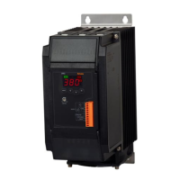
| Model | SPR3 Series |
| Category | Controller |
| Language | English |