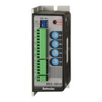
①
Bracket (except rated load current 100A/150A models)
②
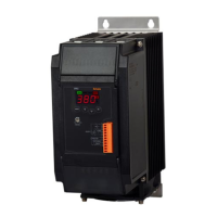
Indicator
Indicator Color Function
RUN Operation indicator Green LED Turns on in the RUN mode.
MAN Manual control indicator Green LED
Turns on when adjusting load output in
the manual control mode.
ALM Alarm indicator Red LED Flashes in alarming status.
OUT Output indicator Red LED Turns on when load control outputs.
③
Display part
:
Displays settings of the front display [
DIS
] parameter in RUN mode, and displays
parameter and setting value in setting mode.
④
Unit indicator
( : Light ON/ : Light OFF)
Indicator
Display
V A
Resistance, load
Voltage
Current
Power
INSTRUCTION MANUAL
Thank you for choosing our Autonics product.
Please read the following safety considerations before use.
Specications
※
1: The weight includes packaging. The weight in parenthesis is for unit only.
※
Environment resistance is rated at no freezing or condensation.
DRW180136AC
Connections
Wire Specication by Load Current
Unit Description
Model
SPR3-1
SPR3-2
SPR3-3
SPR3-4
Control phase 3-phase
Rated load voltage (50/60Hz)
110VAC
ᜠ
220VAC
ᜠ
380VAC
ᜠ
440VAC
ᜠ
Power supply 100-240VAC
ᜠ
50/60Hz
Min. load current 1A
Permissible voltage range 90 to 110% of rated voltage
Power consumption
Rated load current 25A/35A/50A: max. 14VA
Rated load current 70A: max. 22VA
Rated load current 100A/150A: max. 32VA
Display method 3-digit 7-segment LED
Indicator
Operation indicator/Manual control indicator: green LED
Alarm indicator/output indicator/unit (V, A) indicator: red LED
Control method
Phase control: normal control mode, constant current/constant voltage/
constant power feedback control mode
Cycle control: xed cycle control mode
ON/OFF control
Applied load
Phase control, ON/OFF control: resistance load, inductive load
Cycle control: resistance load
Control input
Auto control: DC4-20mA, 1-5VDC
ᜡ
, ON/OFF contact (no-voltage input),
pulse voltage (5-12VDC
ᜡ
)
Manual control: outside adjuster (10kΩ), inside adjuster (output limit)
Digital input (DI) RUN/STOP switching, AUTO/MAN switching, RESET
Output
Alarm 250VAC
ᜠ
3A, 30VDC
ᜡ
3A, 1c resistive load
Communication
RS485 communication output (Modbus RTU method), max. connection: 31 units
Output range
Phase control: 0 to 98% Cycle control: 0 to 100% ON/OFF control: 0%, 100%
Output accuracy
Normal control
: within ±10% F.S. of rated load voltage
Constant current
feedback control
: within ±3% F.S. of rated load current
Constant voltage
feedback control
: within ±3% F.S. of rated load voltage
Constant power
feedback control
: within ±3% F.S. of rated load power
Set method
By front keys, by communication
Functions
Output limit (OUT ADJ), AUTO/MAN selection, control method selection, RESET,
SOFT START, SOFT UP/DOWN, output high/low limit, input correction, input
slope correction, monitoring (control input, load voltage/current/power/resistance,
power supply frequency, heatsink temperature)
Alarm
Overcurrent alarm, overvoltage alarm, fuse break alarm, SCR error alarm,
heater break alarm, heatsink overheat alarm
Cooling method
Rated load current 25A/35A/50A: natural cooling
Rated load current 70A/100A/150A: forced air cooling (with the cooling fan)
Insulation resistance Over 200MΩ (at 500VDC megger)
Dielectric strength 2,000VAC 50/60Hz for 1 min (between input terminals and power terminals)
Output leakage current Max. 10mArms
Noise immunity ±2kV the square wave noise (pulse width: 1
㎲
) by the noise simulator
Memory retention Approx. 10 years (when using non-volatile semiconductor memory type)
Vibration
Mechanical
0.75mm amplitude at frequency of 5 to 55Hz in each X, Y, Z direction for 2 hours
Malfunction
0.5mm amplitude at frequency of 5 to 55Hz in each X, Y, Z direction for 10 min
Environ
ment
Ambient temp. -10 to 55
℃
, storage: -20 to 80
℃
Ambient humi. 35 to 85%RH, storage: 35 to 85%RH
Accessory 11-pin connector, insulating barrier: 4
Approval
ᜢ
Weight
※
1
Rated load current 25A/35A/50A: approx. 4.9kg (approx. 4.1kg)
Rated load current 70A: approx. 5kg (approx. 4.2kg)
Rated load current 100A/150A: approx. 9.7kg (approx. 8.7kg)
Spacing
※
When installing multiple power controllers, please
keep space at least 50mm in horizontal and 100mm in
vertical between power controllers for heat radiation.
While supplying power to the load or right after turning
off the power of the load, do not touch the body and
heatsink. Failure to follow this instruction may result in
a burn due to the high temperature.
High Temperature Caution
Safety Considerations
1. Fail-safe device must be installed when using the unit with machinery that may cause
serious injury or substantial economic loss. (e.g. nuclear power control, medical equipment,
ships, vehicles, railways, aircraft, combustion apparatus, safety equipment, crime/disaster
prevention devices, etc.)
Failure to follow this instruction may result in re, personal injury, or economic loss.
2. Install on the device panel, and ground to the heat sink or bracket separately.
Failure to follow this instruction may result in electric shock or re.
3. Do not connect, repair, or inspect the unit while connected to a power source.
Failure to follow this instruction may result in electric shock or re.
4. Check 'Connections' before wiring.
Failure to follow this instruction may result in re.
5. Do not disassemble or modify the unit.
Failure to follow this instruction may result in electric shock or re.
Warning
1. Use the unit within the rated specications.
Failure to follow this instruction may result in re or product damage.
2. Use dry cloth to clean the unit, and do not use water or organic solvent.
Failure to follow this instruction may result in electric shock or re.
3. Do not use the unit in the place where ammable/explosive/corrosive gas, humidity, direct
sunlight, radiant heat, vibration, impact, or salinity may be present.
Failure to follow this instruction may result in re or explosion.
4. Keep metal chip, dust, and wire residue from owing into the unit.
Failure to follow this instruction may result in re or product damage.
5. Since leakage current still ows right after turning off the power or in the output OFF status,
do not touch the load terminal.
Failure to follow this instruction may result in electric shock.
Caution
※
The above specifications are subject to change and some models may be discontinued
without notice.
※
Be sure to follow cautions written in the instruction manual, user manual, and the
technical descriptions (catalog, homepage).
LED Display Slim Power Controller
SPR3 Series
※
1: This is only for models with RS485 communication output (SPR3- T ).
※
2: When connecting noise lter and capacitor, it is appropriate for EMC.
CAP : Rated load voltage 110VAC-220VAC → 1uF/250VAC
: Rated load voltage 380VAC-440VAC → 0.47uF/500VAC
※
Tighten the terminal screw with the below tightening torque.
Rated load
current
Specication
Alarm output/
power input
Load input/output
25A, 35A,
50A, 70A
Screw M3 M6
Tightening torque 0.5N
.
m 5.5 to 6.0N
.
m
100A, 150A
Screw M3 M8
Tightening torque 0.5N
.
m 6.5 to 7.0N
.
m
<Crimp terminal>
a
b
c
Terminal
type
Terminal
number
a b c
Input
(11-pin)
1 to 11 6 to 7 Max. 1.5 Max. 3.5
※
Use crimp terminals or terminals of size specied below.
a
b
<Round>
Terminal type a b
Alarm output/power input Min. 3.0 Max. 6.0
Load
input/output
Rated load current
25A/35A/50A/70A
Min. 6.0 Max. 16.0
Rated load current
100A/150A
Min. 8.0 Max. 26.0
(unit: mm)
⑤
key:
Enters parameter group, returns to RUN mode, moves
parameters, and saves the setting value.
⑥
Setting value adjustment key
: Enters SV setting mode and move digits.
⑦
Output limit adjuster (OUT ADJ)
: Limits output from 0 to 100%.
⑧
11-pin connector terminal
⑨
Terminal cover
⑩
R, S, T load input terminals
⑪
Alarm output and power input terminals
⑫
U, V, W load output terminals
⑬
Cooling fan: For models with the rated load current of 70A/100A/150A, a cooling fan is attached.
⑭
Heatsink: In case of rated load current 100A/150A models, there are mounting holes on the right/left.
Rated load current
Wire specication
Alarm output/power input Load input/output
25A/35A/50A/70A
AWG 18 to 14
AWG 13 to 4
100A/150A AWG 4 to 2/0
(unit: mm)
※
Please observe all safety considerations for safe and proper product operation to avoid hazards.
※
symbol represents caution due to special circumstances in which hazards may occur.
Warning
Failure to follow these instructions may result in serious injury or death.
Caution
Failure to follow these instructions may result in personal injury or product damage.
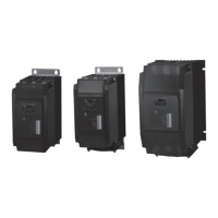
Rated load current 25A/35A/50A
Rated load current 100A/150A
Rated load current 70A
Dimensions
Control input/Comm. output
Alarm output/power input
Load input/output
Alarm Output
(250VAC 3A 1c)
(30VDC 3A 1c)
Resistive Load
100-240VAC
50/60Hz
1 2 3 4 5
N.C. N.O. LCOM N
※
2
※
2
Noise lter
Rapid
fuse
CAP
S
R T
V
U W
※
1
①
②
③
④
⑤
⑥
⑦
⑧
⑨
⑩
⑪
VR
ON/OFF
4-20mA
1-5
VDC
RUN/STOP
AUTO/MAN
RESET
RS485
A(+)
B(-)
Load
Load
Load
Ordering Information
※
1: Product is not equipped with a rapid fuse inside. Install the suitable fuse for rated load current of
the model separately.
(The performance of the product is guaranteed only when using the fuse provided by us.)
SPR
Solid State Power Regulator
(slim type)
N
Non-fuse
※1
F
Fuse
N
Normal control
F
Normal/constant current/constant
voltage/constant power control
N
Alarm output
T
Alarm+RS485 comm. output
1
110VAC
2
220VAC
3
380VAC
4
440VAC
3
3-phase
25
25A
35
35A
50
50A
70
70A
100
100A
150
150A
Control phase
Item
Rated load current
Rated load voltage
Fuse
Option output
Feedback
control
Removing the Case
Replacement of Fuse
For replacing the fuse, please use the recommended fuse which has the below specications.
(manufacture: BUSSMANN)
※
The performance of the product is guaranteed only when using the fuse provided by us.
Recommended fuse specifications
Spec. of fuse fixing bolts
Rated load current Spec. of bolts
25A, 35A, 50A, 70A M6
100A Top: M8 / Bottom: M6
150A M8
Rated load
current
Model
Rated load
current
Model
25A 50FE 50A 80ET
35A 63ET 70A 100FE
Case xing bolts
Spec. of case fixing bolts
Rated load current Spec. of bolts
25A, 35A, 50A, 70A M3
100A, 150A M4
Fuse xing bolts
Fuse
3 T FSPR 702 F
Rated load
current
Model
100A 660GH-160
150A 660GH-200
(manufacture: HINODE)
①
⑧
⑦
⑤
③
②
⑥
④
⑨
⑨
⑬
U V W
⑪
⑫
⑭
⑬
⑩
R S T
100
100
4-Ø6
50
227
203.1
261
4-Ø6
6.8
243.6
200
21.8
68
92.2
105
80
80
250
203.1
261
4-Ø6
6.8
266.6
200
21.8
25
68
92.2
105
80
80
233.2
326.5
4-Ø6.5
270
210 30
140
158
170
80
80
25
(unit: mm)
Rated load current A B C
25A, 35A, 50A 30 28.2 300
70A 30 28.2 300
100A, 150A 40.5 50 370
Insulating barrier
With the insulating barrier
55
A
B
40
2.5
3.8
1.5
42.5
C
※
It is recommended to use the included interphase barriers
for insulation between phases and reduce influence from
conductive material.
Panel
Panel