EasyManua.ls Logo

Autonics SFC-R Series - User Manual

Autonics SFC-R Series
13 pages
Print Icon
To Next Page IconTo Next Page
Loading...
-|Transparent Guide|-
DRW190758AE
󹮭󹮭󹮶󹮭
󹮭󹮭
󹮸󹮶



󹮭󹃑󹮭󹮭󹮭󹮭󹮭󹮭󹮭󹮭󹮭󹮭󹮭
󹮭󹮭󹮭󹮭󹮭󹮭󹮭
󹮭󹮭󹮭






󹃐










 



󹃑
 










󹃑
󹃑
 󹃒󹃒

󹃑󹃑

 

󹃑
 

󹃑󹃑


 󹃓


󹃑
 
󹃑

 




 

󹃑
 󹃒

󹃑
 
󹃒
󹃑
 

󹃑
 
󹃑

 

󹃑
 


Question and Answer IconNeed help?

Do you have a question about the Autonics SFC-R Series and is the answer not in the manual?

Summary

Safety Considerations

Major Features

Cautions during Use

Dimensions

Mounting with bolts

Instructions for attaching the product to a panel using bolts.

Mounting on DIN Rail

Instructions for mounting the product on a DIN rail.

Removing on DIN Rail

Instructions for removing the product from a DIN rail.

Indicators

Setting Switches

Setting Switch for off-delay time

Configuration of the off-delay time for safety outputs.

Setting switch for function

Configuration of various functions for advanced/non-contact units.

Connections

Wiring of Input

Details on connecting input signals and power supply.

Wiring of Output

Details on connecting safety and auxiliary outputs.

Logical AND Connections

Configuration for logical AND connections between units.

Check and Maintenance

Check installation conditions

Verification of the product's installation environment and safety.

Check wiring connection

Verification of the product's wiring for safety and functionality.

Safety system-check in operation

Testing the safety system's operational integrity.

Daily inspection

Routine checks performed daily for product safety.

Regular inspection

Periodic checks performed for product safety and maintenance.

Error Indication

Interpreting error codes and indicators for troubleshooting.

Failure Rate

Connection Examples

Advanced unit-Safety light curtain

Example wiring for an advanced unit with a safety light curtain.

Advanced unit-Safety door lock switch, Expansion relay unit

Example wiring for advanced unit, door lock switch, and expansion relay.

Non-contact door switch unit-Safety non-contact door switch

Example wiring for non-contact unit and safety non-contact door switch.

Basic unit-Safety emergency stop switch, Non-contact door switch unit-Safety non-contact door switch

Example wiring for basic unit, emergency stop, and non-contact door switch.

Relay unit-Safety emergency stop switch

Example wiring for a relay unit with a safety emergency stop switch.

Relay unit-Safety light curtain

Example wiring for a relay unit with a safety light curtain.

Relay unit-Safety door lock switch

Example wiring for a relay unit with a safety door lock switch.

Overview

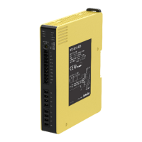
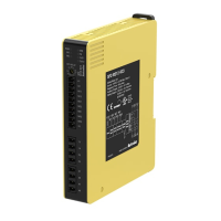
This document describes the Autonics SFC / SFC-R Series Safety Controllers and Safety Relay Units, designed to enhance safety in industrial environments. These devices are crucial for applications requiring high safety integrity levels, such as those involving machinery that could cause serious injury or economic loss.

Function Description

The SFC / SFC-R Series units serve as central components in safety control systems, monitoring various safety inputs and providing safety outputs to control hazardous machinery. They are designed to achieve high safety performance levels, conforming to international safety regulations and standards such as SIL3, SIL CL3, PLe, CE, UL Listed, and S Mark.

The core function of these units is to process signals from safety input devices like emergency stop buttons, safety light curtains, safety door lock switches, and non-contact door switches. Based on these inputs and configured logic, the controllers activate or deactivate safety outputs, which typically control contactors or motor controllers to bring machinery to a safe state.

Different models within the series offer various output types, including P-channel FET safety outputs for instantaneous or off-delay control, and relay contact safety outputs, also with instantaneous or off-delay capabilities. The off-delay feature allows for controlled shutdown sequences, crucial for applications where immediate power cut-off could be hazardous or damaging.

Auxiliary outputs (X1, X2) are also provided. Auxiliary output 1 (X1) mirrors the state of the instantaneous safety outputs, turning ON when they are ON and OFF when they are OFF. Auxiliary output 2 (X2) indicates an error condition, turning ON when the ERR indicator is active. It is critical to note that these auxiliary outputs are non-safety outputs and must not be used for safety-related purposes.

The units support various connection configurations, including logic (AND) connections for integrating multiple safety functions and expansion relay unit connections to increase the number of available safety outputs. This modularity allows for flexible system design to meet diverse application requirements.

Usage Features

The SFC / SFC-R Series units are designed with user-friendly features to facilitate installation, operation, and troubleshooting.

  • Compact Design: The slim size (17.5 / 22.5 / 35 mm) of these units helps save installation space in control panels, which is particularly beneficial in crowded industrial environments.
  • Visual Status Indicators: Multiple LED indicators are integrated to display the status of various functions, including power, safety inputs, logic inputs, error conditions, feedback, and outputs. These visual cues allow operators to quickly assess the operational state of the device and identify potential issues.
  • Connection Options: Both screw and screwless connection models are available, offering flexibility based on installation preferences and maintenance requirements. Screwless terminals can expedite wiring and reduce the risk of loose connections due to vibration.
  • Configurable Off-Delay: The units offer configurable off-delay output times, which can be set for advanced applications, non-contact door switches, or relay output models. This feature is essential for applications requiring a controlled stop rather than an abrupt shutdown, allowing for safe deceleration or process completion.
  • Logic and Expansion Capabilities: The ability to perform logic (AND) connections allows for the integration of multiple safety inputs into a single safety function. Furthermore, the option to connect expansion relay units significantly extends the number of available safety outputs, making the system scalable for complex machinery.
  • Compliance with Standards: The product structure is designed to conform to international safety regulations and standards, ensuring reliability and acceptance in various global markets. This compliance simplifies the process of achieving machine safety certifications.
  • Installation Flexibility: The units can be installed on a device panel or DIN rail inside a control room with an IP54 or higher protection structure. For DIN rail mounting, an End plate (sold separately) is recommended for secure fixation. In environments with high vibration or shock, screw mounting to the panel is advised to prevent dislodgement.
  • Responsible Operation: The manual emphasizes the importance of a "responsible person" who is fully knowledgeable about the product's installation, settings, use, and maintenance, and familiar with relevant laws and standards. This person is also responsible for educating machine users on proper operation and reporting errors.

Maintenance Features

Effective maintenance is crucial for ensuring the continuous safe operation of safety devices. The SFC / SFC-R Series includes features and recommendations to support this.

  • Error Indication System: When an error occurs, the ERR indicator, along with other relevant indicators, will turn ON or flash to signal the cause of the error. The manual provides a detailed table linking specific indicator states to potential causes and recommended check and measure actions. This system aids in rapid diagnosis and resolution of issues, minimizing downtime and maintaining safety integrity.
  • Regular Inspections: The manual mandates daily and regular inspections (every six months) to ensure the product's continued proper function and to prevent malfunctions that could lead to personal injury or economic loss. These inspections cover several key areas:
    • Installation Conditions: Verifying that the product and connected safety sensors are installed at the calculated safety distance from hazardous zones, and that the installation environment does not cause material deformation. It also checks for secure fixation on DIN rails or panels and absence of product damage.
    • Wiring Connection: Confirming that the power supply for safety-related functions is 24VDC and meets specifications, polarity is correct, wiring is undamaged, and connections are appropriate for the intended purpose. It also ensures that auxiliary outputs are not connected to safety-related parts of the control system.
    • Safety System-Check in Operation: This involves inspecting the system without an operator in the hazardous zone, verifying that the safety system stops immediately when the safety input signal is OFF, and that it maintains its status during power shutdowns. It also checks that the actual machine response time is less than the calculated time.
  • Troubleshooting Guidance: The comprehensive error indication table and troubleshooting steps provided in the manual empower maintenance personnel to address common issues effectively. This self-help capability reduces reliance on external support and speeds up problem resolution.
  • Product Longevity: By adhering to the recommended installation and maintenance practices, users can maximize the lifespan and reliability of the safety controllers, ensuring long-term safety performance.
  • Manufacturer Support: In cases where the recommended measures are not effective, users are advised to contact Autonics, indicating that manufacturer support is available for complex issues or internal circuit failures.

Autonics SFC-R Series Specifications

General IconGeneral
Control MethodPID control
Input TypeThermocouple, RTD
Output TypeRelay, Current, Voltage, SSR drive
DisplayLED
Power Supply100-240V AC, 24V AC/DC
CommunicationRS485 (Modbus RTU)
Output RatingCurrent: 4-20 mA
Set Point RangeDepends on input type
Ambient Humidity35-85% RH (non-condensing)

Related product manuals