Do you have a question about the Autonics TZN4M and is the answer not in the manual?
Defines the available control output types, such as Relay, SSR drive voltage, and Current output.
Specifies the available power supply ranges, including 24VAC/24-48VDC and 100-240VAC.
Details the various auxiliary output functions, including event outputs and PV transmission.
Lists the different physical dimensions and mounting types available for the controller series.
Indicates the number of digits available for the controller's display.
Details supported input types like RTD, Thermocouple, and Analog, along with their respective ranges.
Outlines the specifications for main outputs like Relay, SSR, and Current, including voltage and current ratings.
Specifies power requirements, allowable voltage ranges, and power consumption for different models.
Covers display accuracy, character size, and communication protocols like RS485.
Lists parameters like control types, hysteresis, PID settings, and alarm configurations.
Provides a detailed wiring diagram for the TZN4S model, showing terminal connections.
Illustrates the terminal connections for the TZN4M controller model.
Shows the specific wiring configurations for TZ4SP and TZ4ST models.
Details the terminal connections for the TZ4M controller model.
Presents the physical dimensions and panel cut-out requirements for TZN4S and TZN4M models.
Shows the physical dimensions and panel cut-out specifications for TZ4W and TZN4W models.
Details the physical dimensions and panel cut-out requirements for TZ4H and TZN4H models.
Presents the physical dimensions and panel cut-out specifications for TZ4L and TZN4L models.
Provides physical dimensions and panel cut-out details for TZ4SP and TZ4ST models.
Details the physical dimensions and panel cut-out requirements for the TZ4M model.
Shows physical dimensions and panel cut-out specifications for TZ4W and TZN4W models.
Presents physical dimensions and panel cut-out details for TZ4H and TZN4H models.
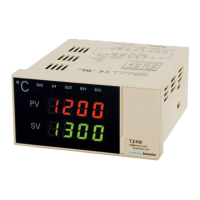
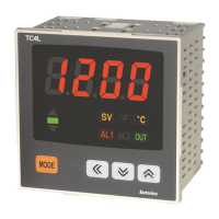
Identifies and describes the components and indicators on the controller's front panel for various models.
Explains the step-by-step process for setting the Secondary Value (SV) on the controller.
Illustrates the flow chart for accessing and configuring parameters in group 1.
Lists the default settings for various parameters within group 1.
Details the various settings and options available in parameter group 2.
Provides the default factory settings for parameters within group 2.
Lists all available input types (Thermocouple, RTD, Analog) and their corresponding temperature ranges.
Explains how to configure internal switches (SW1, SW2) for different sensor inputs.
Describes how alarm outputs operate based on deviation or absolute values compared to setpoints.
Details different alarm modes like standard, latch, standby, and their sequence operations.
Explains the PID auto-tuning process, modes, and execution for optimal system response.
Details the sub output capabilities, including relay contact output and alarm modes.
Describes the function that detects a broken or open sensor line and triggers an output.
Explains the function to diagnose abnormal temperature control by detecting lack of system change.
Lists possible error messages (LLLL, HHHH, OPEn) and their meanings.
Details the two-position control method where output switches based on PV vs. SV.
Explains the manual reset feature used in proportional control to correct deviations.
Describes how to set the decimal point display for analog input signals.
Covers the high-speed (PIDF) and low-speed (PIDS) PID control modes for optimal response.
Details the RS485 communication protocol for transmitting data and setting values.
Explains the heat and cool functions for temperature control and their proper application.
Describes how the SV2 function changes control temperature using external relay signals.
Details the ramp function for delaying temperature rise or fall times.
Explains how to correct deviations occurring from temperature sensors for accurate readings.
Guides on selecting input types for converters and connecting analog outputs.
Illustrates the application of relay output type, including wiring and protection measures.
Details the application of SSR output type, including selection and usage precautions.
Explains the application of DC4-20mA current output and load capacity considerations.
Describes the application of DC4-20mA transmission output for recording instruments.
Shows the application of RS485 communication output and its connection to converters/PCs.
Details communication interface specifications like standard, method, distance, and speed.
Explains the system ordering, wiring requirements, and communication control setup.
Defines the structure and usage of commands for reading and writing settings.
Shows the format of responses to commands, including ACK and data transmission.
Describes how to write negative setting values and other communication responses.
Guides on checking load (heater) operation and diagnosing issues with the OUT lamp.
Explains the 'OPEn' error message and steps to diagnose sensor connectivity issues.
Describes the 'Err0' message and precautions against strong external noise.
Provides essential precautions for safe and effective use, including wiring, installation, and environmental conditions.
| Model | TZN4M |
|---|---|
| Control Method | PID Control |
| Input Type | Thermocouple, RTD, Voltage, Current |
| Output Type | Relay, Voltage, Current |
| Number of Inputs | 1 |
| Mounting | Panel Mount |
| Display | LED |
| Power Supply | 100-240VAC |
| Control Output | Relay |
| Accuracy | ±0.3% FS ±1 digit |
| Operating Temperature | 0 to 50°C |
| Protection Structure | IP65 |
| Communication | RS-485 |
| Storage Temperature | -20 to 60 ℃ |
| Humidity | 35 to 85% RH (non-condensing) |