H-87
(A)
Photo
electric
sensor
(B)
Fiber
optic
sensor
(C)
Door/Area
sensor
(D)
Proximity
sensor
(E)
Pressure
sensor
(F)
Rotary
encoder
(G)
Connector/
Socket
(H)
Temp.
controller
(I)
SSR/
Power
controller
(J)
Counter
(K)
Timer
(L)
Panel
meter
(M)
Tacho/
Speed/ Pulse
meter
(N)
Display
unit
(O)
Sensor
controller
(P)
Switching
mode power
supply
(Q)
Stepper
motor&
Driver&Controller
(R)
Graphic/
Logic
panel
(S)
Field
network
device
(T)
Software
(U)
Other
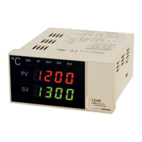
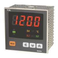
Dual PID Auto Tuning Control
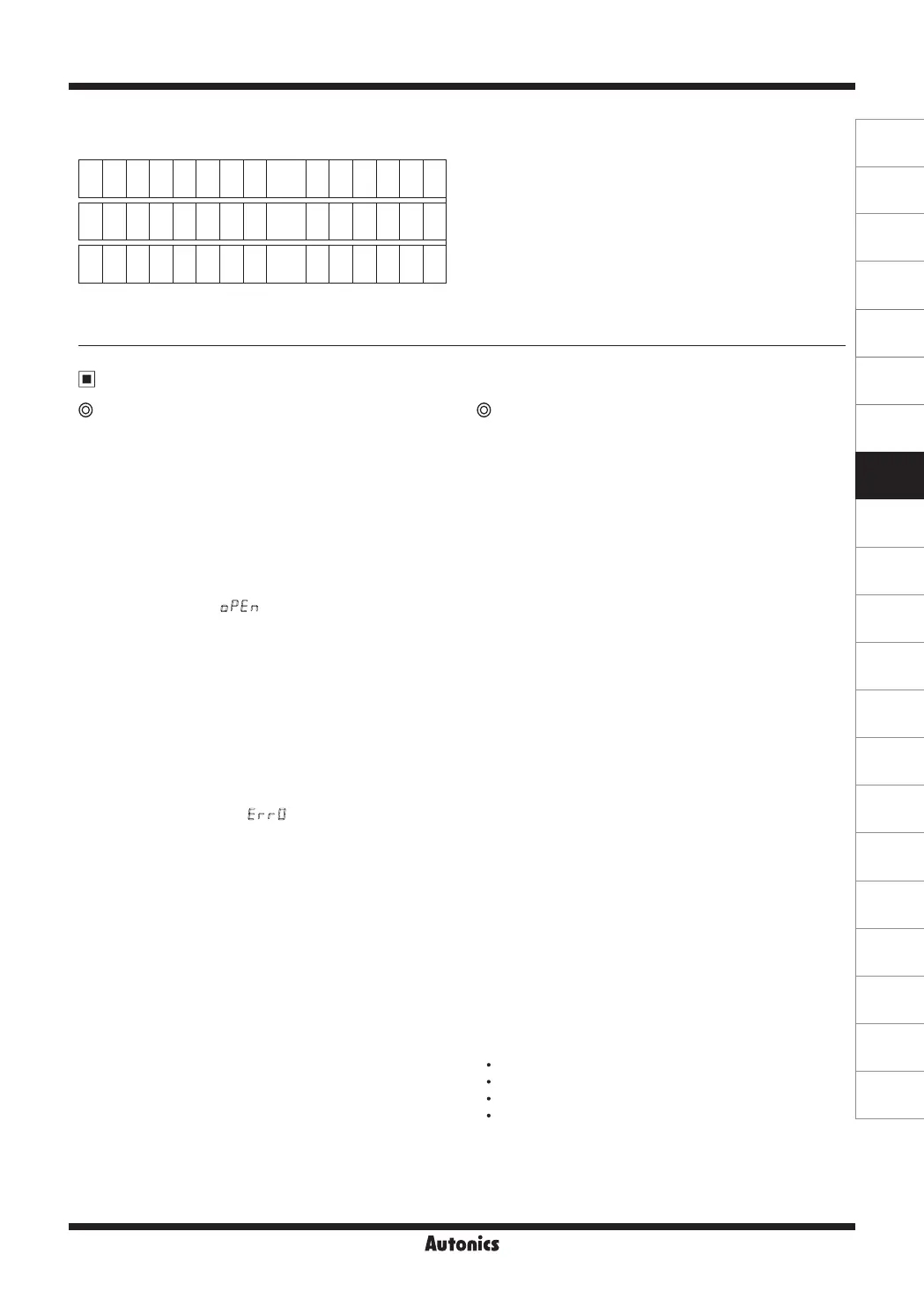
● Write of setting value
In case setting value is -100
A
C
K
S
T
X
0 1 W D S 0 Symbol 10
3
10
2
10
1
10
0
E
T
X
F
S
C
A
C
K
S
T
X
0 1 W D S 0
-
0 1 0 0
E
T
X
B
C
C
06 02 30 31 57 44 53 30 2D 30 31 30 30 03
B
C
C
● Others: In case of no response of ACK
①
When the address is not the same after receiving STX.
②
When receiving buffer overflow is occurred.
③
When the baud rate or others communication setting
value are not the same.
● When there are no ACK response
①
Check the status of lines
②
Check the communication condition(Setting value)
③
When assuming the problem is due to noise, try to
operate communication 3 times more until recovery.
④
When occurred communication failure frequently,
please adjust the communicating speed.
Proper usage
Simple "error" diagnosis Caution for using
● When the load (Heater etc) is not operated
Please check operation of the OUT lamp located in front
panel of the unit.
If the OUT lamp does not operate, please check the
parameter of all programmed mode.
If lamp is operating, please check the output(Relay, SSR
drive voltage) after separating output line from the unit.
But, the out lamp is not operated for DC4-20mA
● When it displays
OPEN
during operation
This is a warning that external sensor is open.
Please turn off the power and check the wire state of the
sensor. If sensor is not open disconnect sensor line from
the unit and short the input +, - terminal. Turn on the
power of the unit and check the controller displays room
temperature.
If this unit cannot display room temperature, this unit is
broken. Please remove this unit and contact our service
center. (When the input mode is thermocouple, it is
available to display room temperature.)
● In case of indicating
ERR0
in display
This Error message is indicated in case of damaging
inner chip program data by outer strong noise.
In this case, please send the unit to our after service
center after removing the unit from system.
Noise protection is designed in this unit, but it does not
stand up strong noise continuously. If bigger noise than
specified(Max. 2kV) flows in the unit, it can be damaged.
● Please use the terminal(M3.5, Max. 7.2mm) when
connecting the AC power source.
● Please use separated line from high voltage line or power
line in order to avoid inductive noise.
● Please install power switch or circuit-breaker in order to
cut power supply off.
● The switch or circuit-breaker should be installed near by
users.
● This unit is designed for temperature controlling only. Do
not apply this unit as a voltage meter or a current meter.
● Be sure to use compensating wire when extending wire
from controller to thermocouple, otherwise a temperature
deviation will occur at the point where wires are connected
to each other.
● In case of using RTD sensor, 3-wire type must be used.
If you need to extend the line, 3-wires must be used
with the same thickness as the line. It might cause
temperature difference if the resistance of line is different.
● In case of making power line and input signal line close,
line lter for noise protection should be installed at power
line and input signal line should be shielded.
● Keep away from the high frequency instruments.(High
frequency welding machine & sewing machine, big
capacitive SCR controller)
● If you want to change the input sensor, reset switches
(SW1, SW2) according to each input specication after
power off. Turn on power and then set sensor mode by
front keys at second ow chart.
● This SSR and current of this controller are insulate from
internal power.
● Do not connect power line to sensor connecting part.
The inner circuit may be damaged.
● Installation environment
It shall be used indoor.
Altitude Max. 2000m.
Pollution Degree 2
Installation Category
Ⅱ
.

 Loading...