H-85
(A)
Photo
electric
sensor
(B)
Fiber
optic
sensor
(C)
Door/Area
sensor
(D)
Proximity
sensor
(E)
Pressure
sensor
(F)
Rotary
encoder
(G)
Connector/
Socket
(H)
Temp.
controller
(I)
SSR/
Power
controller
(J)
Counter
(K)
Timer
(L)
Panel
meter
(M)
Tacho/
Speed/ Pulse
meter
(N)
Display
unit
(O)
Sensor
controller
(P)
Switching
mode power
supply
(Q)
Stepper
motor&
Driver&Controller
(R)
Graphic/
Logic
panel
(S)
Field
network
device
(T)
Software
(U)
Other
Dual PID Auto Tuning Control
Equipment
to be
controlled
Converter
Analog output
1-5VDC
0-10VDC
DC4-20
mA
TZ
Series
SSR
Load
power
Power
Voltage
output
terminal
+
-
I
N
P
U
T
L
O
A
D
T
TZ
Series
DC4-20
mA
LOAD 600Ω Max.
Power controller
Load
power
Load
Current
output
terminal
U
W
R
+
-
TZ
Series
Recording instrument
/Panel meter
DC4-20
mA
IN
Tranmission
output
terminal
+ +
- -
RS485
PC
RxD
RxD
TxD TxD
Gnd
Gnd
IN
TZ/TZN
Series
Converter
Communi
cation
output
terminal
+
-
TZ
Series
Relay contact terminal
Heater
Power
L
C
H
Magnet or
Relay contact
Condenser
0.1
㎌
630V
A
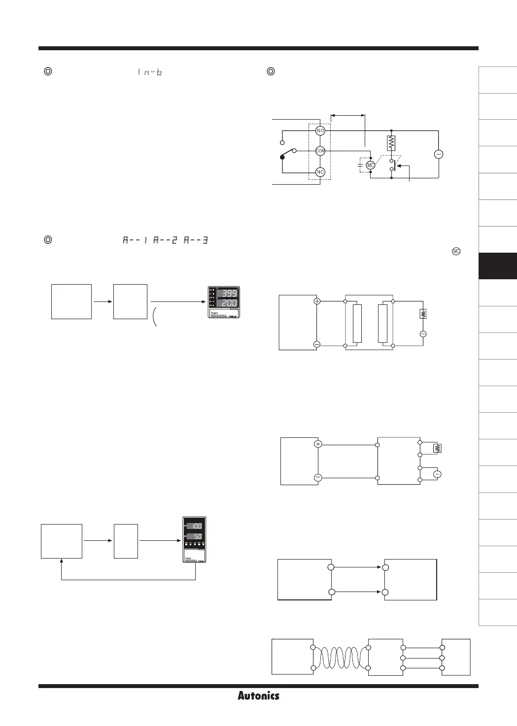
Input correction [
IN-B
]
Input correction is to correct deviation occurred from
temperature sensor such as thermocouples, RTD, Analog
sensor etc. If you check the deviation of every temperature
sensor precisely, it can measure temperature accurately.
● Input revise can be set at
IN-B
mode in parameter 1
group.
● Use this mode after measuring deviation occurred
from temperature sensor exactly. Because if measured
deviation value is not corrected, dis-played temperature
may be too high or too low.
● Set range: -49 to 50
℃
(-50.0 to 50.0
℃
)
● When you set the Input revise value, you may need
to record it, because it will be useful when performing
maintenance.
Analog input [
A--1
,
A--2
,
A--3
]
● In case of measuring or controlling humidity & pressure,
flux, etc, it uses the proper converter which is converting
the measuring value to DC4-20mA or 1-5VDC or 0-10VDC.
● To use analog output of converter as controller input,
select the input type as same as analog output
conditions. (This should be operated in power-off status.)
● This unit has the mode for the converter built-in.
● Please select
A--1
(0-10VDC) or
A--2
(1-5VDC)
or
A--3
(DC4-20
mA
) in selection mode of input in parameter 2 group.
● Set the input value by High scale
[
H-SC
]
and Low scale
[
L-SC
]
mode.
● Please connect the analog output of the converte to the
temperature sensor terminal of the controller. Please be
cautious of the polarity.
● After the procedure, it is controlled same with temperature
control.
● Example of usage
Output connections
●
Application of relay output type
Keep power relay as far away as possible from TZ/TZN
Series
. If wires length of A is short, electromotive force
occurred from a coil of magnet switch & power relay may
flow in power line of the unit, it may cause malfunction.
If wires length of A is short, please connect a mylar
condenser 104(630V) across coil of the power relay "
" to
protect electromotive force.
●
Application of SSR output type
※
SSR should be selected by the capacity of load,
otherwise, it may short-circuit and result in a fire. Indirect
heated should be used with SSR for efficient working.
※
Please use a cooling plate or it may cause the capability
deterioration, breakdown of SSR for a long usage.
●
Application of current output(DC4-20mA)
※
It is important to select SCR unit after checking the capacity
of the load.
※
If the capacity is exceeded, it may cause a fire.
●
Application of communication output(RS485)
●
Application of transmission output(DC4-20mA)
For more information about output, refer to the H-139 page.
Pressure
sensor
Pressure
Temperature
controller
Feedback
IN-T
setting
:
A--3
H-SC
setting
:
100
L-SC
setting
:
0
DC4-20mA
Converter
Control
system
(0 to 100kg)

 Loading...