RS485 Communication Output
Cautions during Use
1. Follow instructions in 'Cautions during Use'. Otherwise, it may cause unexpected accidents.
2. Use the product, after 3 sec of supplying power.
3. Before use, set the mode and function according to the specification. Especially, be cautious that the product
does not operate when OUT ADJ. is set to 0%. Since changing the mode/parameter during operation may
result in malfunction, set the mode and function after disconnecting load output.
4. Re-supply the power to the unit after the unit is discharged completely.
Failure to follow this instruction may result in malfunction.
5. To ensure the reliability of the product, install the product on the panel or metal surface vertically to the ground.
6. Install the unit in the well ventilated place.
7. While supplying power to the load or right after turning off the power of the load, do not touch the body and
heat sink. Failure to follow this instruction may result in a burn due to the high temperature.
8. Install a power switch or circuit breaker in the easily accessible place for supplying or disconnecting the power.
9. Do not wire to terminals which are not used.
10. Since inter element can be damaged when using with coil load, inductive load, etc., the inrush current must
be under the rated load current.
11. Do not use near the equipment which generates strong magnetic force or high frequency noise.
12. This unit may be used in the following environments.
①
Indoors (in the environment condition rated in 'Specifications')
②
Altitude max. 2,000m
③
Pollution degree 2
④
Installation category III
※
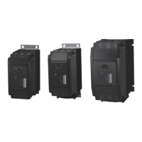
Applicable for models with RS485 communication output through option output (SPR3-
T
).
Please refer to '
Ordering Information'.
1. Communication Specifications
Comm. protocol Modbus RTU
Comm. speed
2400, 4800, 9600, 19200,
38400 bps
Connection method RS485
Application standard
Compliance with EIA RS485 Comm. response time
5 to 99ms (default: 20ms)
Max. connections 31 units (address: 1 to 99) Start bit 1-bit (xed)
Synchronization method
Asynchronous Data bit 8-bit (xed)
Comm. method Two-wire half duplex Parity bit None, Even, Odd
Comm. distance Max. 800m Stop bit 1-bit, 2-bit
2.
Application of system organization
※
It is recommended to use Autonics communication converter; SCM-WF48 (Wi-Fi to RS485·USB wireless
communication converter, sold separately), SCM-US48I (USB to RS485 converter, sold separately),
SCM-38I (RS232C to RS485 converter, sold separately). Please use twisted pair wire, which is suitable
for RS485 communication, for SCM-WF48, SCM-US48I and SCM-38I.
Terminating
resistance
(100 to 120Ω)
B(-)
A(+)
ON OFF
A(+)
RS485
DEVICE
#1
RS485
DEVICE
#2
RS485
DEVICE
#30
RS485
DEVICE
#31
A(+) A(+)B(-) B(-) B(-)
Computer
RS485
Comm.
converter
RS232C/
USB/Wi-Fi
Major Products
Photoelectric Sensors Temperature Controllers
Fiber Optic Sensors Temperature/Humidity Transducers
Door Sensors SSRs/Power Controllers
Door Side Sensors Counters
Area Sensors Timers
Proximity Sensors Panel Meters
Pressure Sensors Tachometer/Pulse (Rate) Meters
Rotary Encoders Display Units
Connector/Sockets Sensor Controllers
Switching Mode Power Supplies
Control Switches/Lamps/Buzzers
I/O Terminal Blocks & Cables
Stepper Motors/Drivers/Motion Controllers
Graphic/Logic Panels
Field Network Devices
Laser Marking System (Fiber, CO
₂
, Nd: YAG)
Laser Welding/Cutting System
http://www.autonics.com
HEADQUARTERS:
18, Bansong-ro 513beon-gil, Haeundae-gu, Busan,
South Korea, 48002
TEL: 82-51-519-3232
E-mail:
sales@autonics.com
DRW180136AC
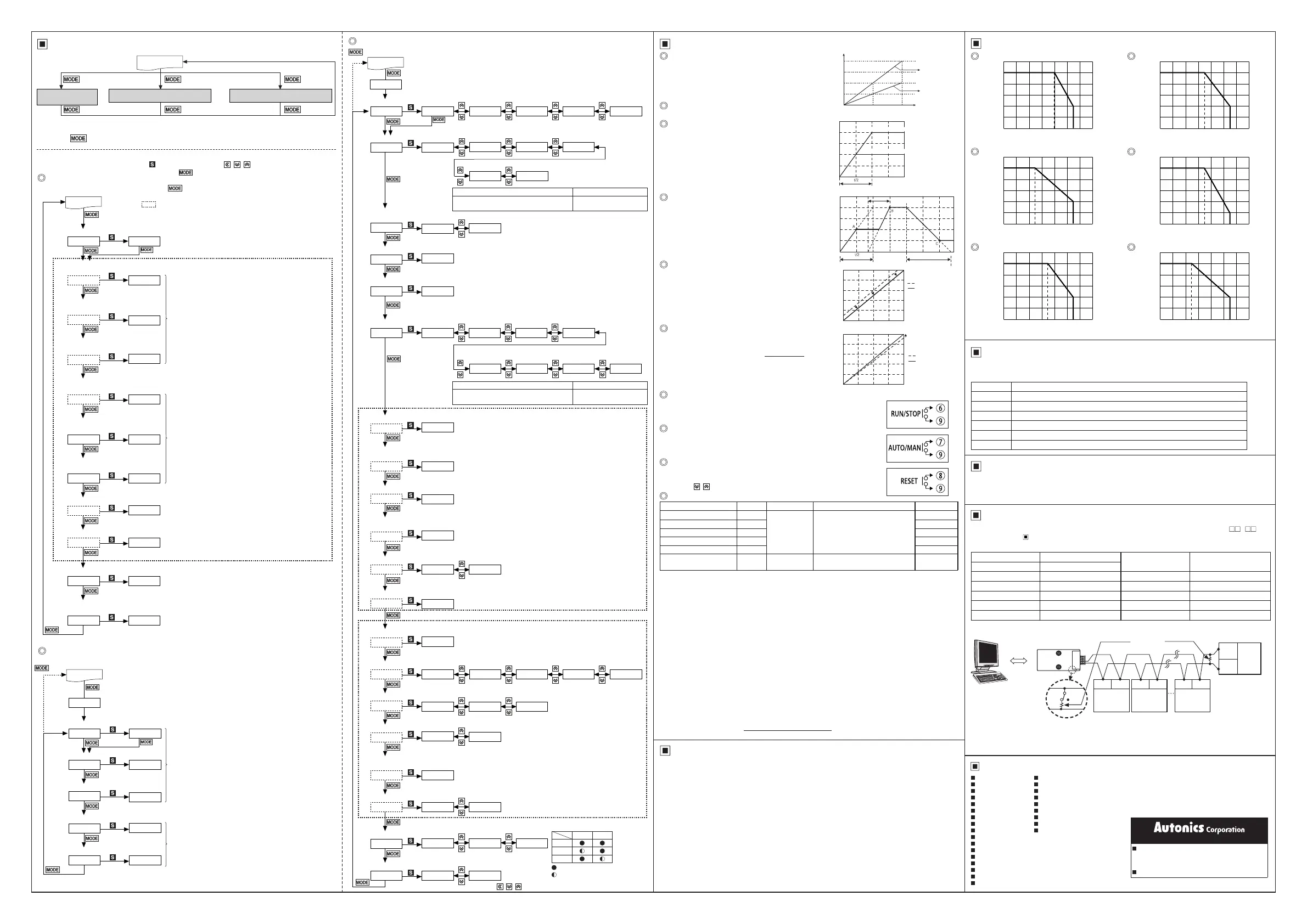
Derating Curve
User Manual for Communication
For the detail information and instructions, please refer to user manual for communication, and be sure
to follow cautions written in the technical descriptions (catalog, homepage).
Visit our homepage (www.autonics.com) to download manuals.
Comprehensive Device Management Program [DAQMaster]
DAQMaster is a comprehensive device management software for setting parameters and monitoring
processes. DAQMaster can be downloaded from our website at www.autonics.com.
Item Minimum specications
System IBM PC compatible computer with Pentium
Ⅲ
or above
Operations Windows 98/NT/XP/Vista/7/8/10
Memory 256MB+
Hard disk 1GB+ of available hard disk space
VGA Resolution: 1024×768 or higher
Others RS232C serial port (9-pin), USB port
Rated load current 25A
25
15
20
10
5
0
0
10 20 30 40 70
Ambient temperature [
℃
]
50 6055
50
30
40
20
10
0
0
10
20 30
40 70
Ambient temperature [
℃
]
Rated load current 50A
25 50 6055
100
60
80
40
20
0
0
10 20 70
Ambient temperature [
℃
]
Rated load current 100A
50 605530 4035
35
21
28
14
7
0
0
10 20
30 40
70
Ambient temperature [
℃
]
Rated load current 35A
35 50 6055
150
90
120
60
30
0
0
Ambient temperature [
℃
]
Rated load current
150A
10
20 30
40 70
25 50 6055
70
42
56
28
14
0
0
10 20
30 40
70
Ambient temperature [
℃
]
Rated load current
70A
35 50 6055
Load current [A]
Load current [A]
Load current [A]
Load current [A]
Load current [A]
Load current [A]
B(-)
A(+)
Monitoring group
Parameter 1 group[
PR1
] Parameter 2 group[
PR2
]
4 sec 2 sec
3 sec 3 sec
RUN mode
※
If there is no key input for 30 sec while setting SV or the parameters, the new settings are ignored,
and the unit will return to RUN mode with previous settings.
※
Hold the key for 3 sec while in setting mode to return to RUN mode.
Parameter Group
Setting range: 0 to 100 sec
※
When control method
[
C-M
]
is
ONF
, settings can not be
changed.
3 sec
2 sec
SOFT START
S-T 000
※
1
SOFT UP
U-T 000
D-T
000
SOFT DOWN
Output low-limit value
L-L
000
Output high-limit value
H-L 100
※
2
PR1
Setting range
: 0% ≤ Output low-limit value[
L-L
] ≤ Output high-limit value[
H-L
] ≤ 100%
Parameter 1 group
RUN mode
Actual input signal [%]
Functions
Output limit (OUT ADJ)
SOFT UP/DOWN [
U-T
/
D-T
]
Input slope correction [
SPN
]
Input correction [
INB
]
RUN/STOP switching
RUN/STOP status of the power controller can be switched with the external
RUN/STOP contact.
In the RUN mode, the operation indicator on the front turns on.
ON/OFF
RESET
In the event of system anomalies and alarms, RESET input restarts the
power controller.(Parameters are not initialized.)
Or, hold the
, keys
for 2 sec, to operates RESET.
ON
AUTO/MANUAL selection
Operation mode (auto control/manual control) of the power controller can be
selected with the external AUTO/MAN contact.
In the manual control mode, the manual control indicator on the front turns on.
ON/OFF
When the power is supplied, this function is able to
protect the load when it controls load (molybdan,
white gold, infrared lamp) with inrush current or the
width of rising temperature in big (SV is big).
SOFT START set time (T) is the required time that
output reaches to 100%, and it is differentiated by
OUT ADJ set value.
Unlike SOFT START which operates only once at
supplying power, this function protects load from the
inrush current in the RUN mode. When reached to
the target output value, operation stops.
Output high limit/low limit value [
H-L
/
L-L
]
This function is to limit output range to protect load.
It compensates the offset between actual input value
and measured input value.
E.g.) When input monitoring value is 5% at 4mA in
DC4-20mA control input, setting
INB
to
-5
calibrates the input monitoring value to 0%.
Measured input signal
[%]
Output
[%]
Output
[%]
Output
[%]
Measured input signal
[%]
SOFT START set time
SOFT DOWN set time
SOFT UP set time
Time
Time
When output applied to load is 100%,
This function will be [Control input (%) × OUT ADJ (%) =
Output] and it controls the power supplied into the load.
Although control input is 100% (5V or 20mA), the output
is the 50% which is proportioned with OUT ADJ.
0 50 100
Control input [%]
Setting value = 50%
Setting value = 100%
100
75
50
25
: Actual input signal (%)
: Input corrected signal (%)
: Actual input signal (%)
: Input corrected signal (%)
Actual input signal [%]
It compensates the gain of the measured 100% input
for actual 100% input value.
Calibrated monitoring value=Monitoring value+
Monitoring value
×
SPN
100-
SPN
E.g.) When the input monitoring value is 99% at 4mA in
DC4-20mA control input,
setting
SPN
to
1
calibrates
the input monitoring value to 100%.
SOFT START [
S-T
]
When output applied to load is 50%,
0
100
50
0
100
50
SOFT START set time
A: SOFT START function nished.
B: SOFT UP function nished.
C: SOFT DOWN function nished.
100
100
100
100
80
80
75
75
60
60
40
40
50
50
20
20
25
25
0
0
※
※
This function can not be used for ON/OFF control method.
※
※
This function can not be used for ON/OFF control method.
※
※
This function can not be used for ON/OFF control method.
Alarm
Type Error Operation Clear alarm
Display priority
SCR error alarm
※
1
SCR
Output stops.
(SCR OFF)
- Re-supply the power.
- RESET
- Switch to STOP mode
1
Overcurrent alarm
※
1
O-C
2
Fuse break alarm
FUS
3
Heatsink overheat alarm
TEM
4
Overvoltage alarm
※
1
O-V
5
Heater break alarm
※
1
H-B
Continues
operation
Automatically cleared when
returning within the setting range.
6
※
1: This is only for feedback control models.
※
For models with alarm output, the error message and alarm indicator ash at the same time, and alarm output turns on.
※
When multiple alarms occur at the same time, the highest priority error message will be displayed based on priority.
1) SCR error alarm
Even though output is 0%, if the current of 10% or more of the rated load current ows for over 3 sec
continuously, SCR error alarm occurs and output stops.
2) Overcurrent alarm [
OCU
/
OCT
]
This function protects the load from overcurrent.
If the current ows over the overcurrent alarm setting value and setting delay time, overcurrent alarm
occurs and output stops.
3) Heatsink overheat alarm
When the temperature of a heatsink is over 85
℃
, heatsink overheat alarm occurs and output stops.
4) Overvoltage alarm [
OVV
/
OVT
]
This function protects the load from overvoltage.
If the current ows over the overvoltage alarm setting value and setting delay time, overvoltage alarm
occurs and output stops.
5) Heater break alarm
[
HBV
]
Comparing the full load resistance value and the current load resistance value, if the current load
resistivity is maintained under the setting value for over 3 sec
continuously
, heater break alarm occurs.
Output does not stop and operates normally.
Current load resistivity(%) =
Full load resistance value
×
100
Current load resistance value
※
1: : Press any key among , , .
※
2: Press the key once after changing the setting value, to save
the setting value and move to the next parameter
※
Hold the key for 3 sec to save the setting value and return to
RUN mode after changing the setting value.
※
Dotted parameters may not appear by model type or other
parameter settings.
Monitoring group
RUN mode
Control input
IN 0
※
1
Load voltage
between U-V line
U-V 380
V-W
380
Load voltage
between V-W line
Load voltage
between W-U line
W-U
380
U-phase
load current
U-A 50
V-phase
load current
V-A 50
W-phase
load current
W-A 50
※
2
Measuring range: 0 to 100%
※
Displayed only for feedback control models.
Measuring range: 0 to rated power range[VA]
Measuring range: Percentage [%] of the currently measured
resistance value compared to the set
resistance value of full load auto recognition.
Load power
L-W
10
Load resistance
L-R 50
Heatsink temp.
TMP 25
Power supply
frequency
FRQ 60
Measuring range: 0 to 100
℃
Measuring range: 50, 60Hz
Measuring range: 0 to rated voltage range[V]
Measuring range: 0 to rated current range[A]
Parameter 2 group
Setting range: 0 to 120%
Setting range: 0 to 100 sec
Setting range: 0 to 120%
Setting range: 10 to 100%
Setting range: 0 to 100 sec
Setting range: -99 to 99%
Setting range: -99 to 99%
3 sec
4 sec
RUN mode
Control input DC4-20mA 1-5VDC 5-12VDC
ON/OFF contact
INT
420
Control method
C-M
E-R
OFF
External output
limit adjuster
OVV
120
Overvoltage alarm value
DIS IN
Front display
HBV
010
Heater break alarm value
Input correction
INB
00
Overvoltage
alarm delay time
OVT
005
Overcurrent alarm value
OCV
120
Input slope correction
SPN 00
Full load auto recognition
F-L OFF
Overcurrent
alarm delay time
OCT 005
1-5 512 ONF
※
2
PR2
RS485 comm.
COM
Load voltage
between
U-V line
Load voltage
between
V-W line
Load voltage
between
W-U line
U-V V-W W-U
ON
ON
Resistance
and input
※
1
※
Displayed only for feedback control models.
Setting range:
Normal control
PA
,
F-C
,
ONF
Feedback control (normal/constant current/
constant voltage/constant power control)
PA
,
V-F
,
C-F
,
W-F
,
F-C
,
ONF
Phase -
Constant
voltage
U-phase
load current
Phase -
Constant
current
V-phase
load current
Phase -
Constant
power
W-phase
load current
Load power
ON/OFF
V-F
U-A
C-F
V-A
W-F
W-A L-W
ONF
Cycle-Fixed
F-C
PA
Phase -
Normal
Setting range:
Normal control
IN
Feedback control (normal/constant current/
constant voltage/constant power control)
IN
,
U-V
,
V-W
,
W-U
,
U-A
,
V-A
,
W-A
,
L-W
EVE ODD
1
Setting range: 1 to 99
※
Displayed only for
modelswithRS485comm.output.
Setting range: 5 to 99ms
Setting range:
Enables Disables
PRT
NON
Comm. parity bit
CM.W EN.A
Comm. write
Comm. stop bit
STP
2
Comm. address
ADR
001
Lock
LOC
OFF
Comm. response
waiting time
RW.T 020
Comm. speed
BPS 96
Parameter reset
INI NO
LC1
YES
DsA
LC2
PR1 PR2
OFF
LC1
LC2
9,600bps 19,200bps 38,400bps 2,400bps 4,800bps
192 384 24 48
: Available to check/set
: Available to check/Unavailable to set
※
Hold the , , keys for 5 sec, to enter parameter reset parameter.

 Loading...