Do you have a question about the Autonics MD5-HD14 and is the answer not in the manual?
Highlights key characteristics of the MD5 series stepper motor drivers, including size, performance, and special functions.
Details on how to select and order specific MD5 driver models based on current, power supply, and resolution.
Presents detailed technical parameters and ratings for the MD5 series drivers, covering electrical and environmental aspects.
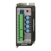
Overview of the MD5-HD14 driver's physical layout, indicators, and terminal connections.
Details on DIP switch functions, RUN current, and STOP current settings for the MD5-HD14 driver.
Configures driver functions like self-diagnosis, pulse input method, and auto current down via DIP switches.
Adjusts the current provided to the motor during operation to match load requirements and optimize torque.
Sets reduced current for the motor when stopped, saving power and heat by utilizing the auto current down function.
Describes the signal indicating the initial motor excitation step and rotation position.
Enables motor excitation release for manual positioning or when external force is applied.
Covers setting the motor's microstep resolution for precise rotation control and step angles.
Selects motor resolution by setting DIP switches for precise step angles, calculated from basic step angle.
Details the input/output signals, wiring diagrams, and component connections for the MD5-HD14 driver.
Illustrates external wiring diagrams for the MD5-HD14 driver, showing connections to motor and user controller.
Provides physical dimensions, mounting hole information, and overall size for the MD5-HD14 driver.
Overview of the MD5-HF14 driver's physical layout, indicators, and terminal connections.
Details on DIP switch functions, RUN current, and STOP current settings for the MD5-HF14 driver.
Configures driver functions like self-diagnosis, pulse input method, and auto current down via DIP switches.
Adjusts the current provided to the motor during operation to match load requirements and optimize torque.
Sets reduced current for the motor when stopped, saving power and heat by utilizing the auto current down function.
Describes the signal indicating the initial motor excitation step and rotation position.
Enables motor excitation release for manual positioning or when external force is applied.
Covers setting the motor's microstep resolution for precise rotation control and step angles.
Selects motor resolution by setting DIP switches for precise step angles, calculated from basic step angle.
Details alarm conditions (overheat, overcurrent) and their indicator lights for the MD5-HF14 driver.
Illustrates external wiring diagrams for the MD5-HF14 driver, showing connections to motor and user controller.
Provides physical dimensions and mounting information for the MD5-HF14 driver.
Overview of the MD5-HF14-AO driver's physical layout, indicators, and terminal connections.
Details on DIP switch functions, RUN current, and STOP current settings for the MD5-HF14-AO driver.
Configures driver functions like self-diagnosis, pulse input method, and auto current down via DIP switches.
Adjusts the current provided to the motor during operation to match load requirements and optimize torque.
Sets reduced current for the motor when stopped, saving power and heat by utilizing the auto current down function.
Enables motor excitation release for manual positioning or when external force is applied.
Covers setting the motor's microstep resolution for precise rotation control and step angles.
Selects motor resolution by setting DIP switches for precise step angles, calculated from basic step angle.
Details alarm conditions (overheat, overcurrent) and their indicator lights for the MD5-HF14-AO driver.
Illustrates external wiring diagrams for the MD5-HF14-AO driver, showing connections to motor and user controller.
Provides physical dimensions and mounting information for the MD5-HF14-AO driver.
Overview of the MD5-HF28 driver's physical layout, indicators, and terminal connections.
Details on DIP switch functions, RUN current, and STOP current settings for the MD5-HF28 driver.
Configures driver functions like self-diagnosis, pulse input method, and auto current down via DIP switches.
Adjusts the current provided to the motor during operation to match load requirements and optimize torque.
Sets reduced current for the motor when stopped, saving power and heat by utilizing the auto current down function.
Describes the signal indicating the initial motor excitation step and rotation position.
Covers setting the motor's microstep resolution for precise rotation control and step angles.
Selects motor resolution by setting DIP switches for precise step angles, calculated from basic step angle.
Details alarm conditions (overheat, overcurrent) and their indicator lights for the MD5-HF28 driver.
Illustrates external wiring diagrams for the MD5-HF28 driver, showing connections to motor and user controller.
Provides physical dimensions and mounting information for the MD5-HF28 driver.
Overview of the MD5-ND14 driver's physical layout, indicators, and terminal connections.
Details on DIP switch functions, RUN current, and STOP current settings for the MD5-ND14 driver.
Configures driver functions like pulse input method and resolution select via DIP switches.
Adjusts the current provided to the motor during operation to match load requirements and optimize torque.
Sets reduced current for the motor when stopped, saving power and heat.
Details the input/output signals, wiring diagrams, and component connections for the MD5-ND14 driver.
Enables motor excitation release for manual positioning or when external force is applied.
Illustrates timing charts for 1-pulse and 2-pulse input methods used for motor control.
Provides physical dimensions and mounting information for the MD5-ND14 driver.
Highlights simultaneous 2/3-axis operation, compact design, and advanced quality of multi-axis drivers.
Highlights key characteristics of the MD5-HD14-2X/3X multi-axis drivers.
Details on selecting 2-axis (2X) or 3-axis (3X) multi-axis drivers.
Presents detailed technical parameters for the MD5-HD14-2X/3X multi-axis drivers.
Details on DIP switch functions, RUN current, and STOP current settings for the multi-axis drivers.
Configures driver functions like self-diagnosis, pulse input method, and auto current down via DIP switches.
Adjusts the current provided to the motor during operation to match load requirements and optimize torque.
Sets reduced current for the motor when stopped, saving power and heat by utilizing the auto current down function.
Covers setting the motor's microstep resolution for precise rotation control and step angles.
Selects motor resolution by setting DIP switches for precise step angles, calculated from basic step angle.
Details the input/output signals, wiring diagrams, and component connections for the multi-axis drivers.
Overview of the MD5-HD14-2X/3X driver's physical layout and terminal connections.
Illustrates external wiring diagrams for the MD5-HD14-2X/3X drivers, showing connections to motor and user controller.
Provides physical dimensions and mounting information for the MD5-HD14-2X/3X multi-axis drivers.
Illustrates timing charts for 1-pulse and 2-pulse input methods used for motor control.
Guidelines for proper signal input, including voltage limits, simultaneous signals, and cable types.
Advice on setting current values to prevent overheating and motor damage, and effects of current down function.
Instructions for rotating the motor when driver power is on or off, emphasizing safety precautions.
Recommendations for signal and motor cable connections, including type, length, and separation from power cables.
Heat protection, ventilation requirements, and installation considerations for optimal driver performance and longevity.
Important notes on setting switches before power supply and during operation to prevent malfunction.
Disclaimer stating that the driver does not include dedicated protection functions for the motor itself.
Specifies suitable environmental conditions for product usage, including altitude and pollution degree.
| Model | MD5-HD14 |
|---|---|
| Category | Controller |
| Number of Inputs | 5 |
| Number of Outputs | 4 |
| Output Type | Relay |
| Communication Interface | RS-485 |
| Operating Temperature | -10°C to 55°C |
| Type | Digital Controller |
| Storage Temperature | -20 to 60℃ |