1. Fail-safe device must be installed when using the unit with machinery that may cause serious injury or
substantial economic loss. (e.g. nuclear power control, medical equipment, ships, vehicles, railways,
aircraft, combustion apparatus, safety equipment, crime/disaster prevention devices, etc.)
Failuretofollowthisinstructionmayresultinre,personalinjury,oreconomicloss.
2. Install on a device panel or to a pressure port directrly to use.
Failuretofollowthisinstructionmayresultinre.
3. Do not connect, repair, or inspect the unit while connected to a power source.
Failuretofollowthisinstructionmayresultinre.
4. Check 'Connections' before wiring.
Failuretofollowthisinstructionmayresultinre.
5. Do not disassemble or modify the unit.
Failuretofollowthisinstructionmayresultinre.
DIGITALPRESSURESENSOR(Pneumatictype)
PSAN SERIES
Safety Considerations
Warning
Caution
Output Operation Mode
Parameter Setting
Preset Setting
Input/Output Circuit and Diagram
Installation
Error
Functions
I N S T R U C T I O N M A N U A L
ThankyouverymuchforselectingAutonicsproducts.
For your safety, please read the following before using.
※
Pleasekeeptheseinstructionsandreviewthembeforeusingthisunit.
※
Thefollowingisanexplanationofthesymbolsusedintheoperationmanual.
Caution:Injuryordangermayoccurunderspecialconditions.
※
Pleaseobservethecautionsthatfollow;
Warning
Seriousinjurymayresultifinstructionsarenotfollowed.
Caution
Productmaybedamaged,orinjurymayresultifinstructionsarenotfollowed.
Specications Setting
Major Products
Display Description Countermeasures
ERR1
Whenexternalpressureisinputwhileadjustingzeropoint.
Tryagainafterremovingexternalpressure.
ERR2
Whenoverloadisappliedoncontroloutput Removeoverload.
ERR3
WhensettingconditionisnotmetinAutosensitivity
settingmode.
Checksettingconditionsandsetproper
settingvalues.
LLLL
WhenappliedpressureexceedsLow-limitofdisplay
pressurerange.
Applypressurewithindisplaypressure
range.
HHHH
WhenappliedpressureexceedsHigh-limitofdisplay
pressurerange.
-HH-
,
-LL-
,
-HL-
Autoshiftcorrectionerror.
Setthecorrectedsettingvaluewithin
settingpressurerange.
Hysteresis mode[
HYS.M
]
Itisabletosetcertainvalueforpressuredetection
level[
ST1
,
ST2
]andhysteresis[
HYS1
,
HYS2
].
Hysteresis mode
Hysteresis-Window comparison output mode
Zero point adjustment
1.Pleasepress + keysforover1sec.atthe
sametimeputtinganappliedpressureinstateofthe
atmosphericpressure.
2.Whenthezeropointadjustmentiscompleted,itwill
display
)0
andreturntoRUNmodeautomatically.
※
Ifexecutingzeropointadjustmentonexternal
pressurebeingatpressureport[
ERR1
] flashes 5
times.Pleaseexecuteitintheatmosphericpressure
afterremovingexternalpressure.
※
Pleaseexecutezeropointadjustmentregularly.
※
1:PSAN- H- Displayedonlywhen
D-IN
is
set to
SHFT
.Autoshiftreferencepressurecanbeset
withindisplayerrorrange.
(Low_Range≤
SH.IN
≤High_Range)
•Low_Range=Min.displaypressure-Min.preset
setting value
•High_Range=Max.displaypressure-Max.preset
setting value
※
Ifpressing + keysforover1sec.incaseofHigh
peak/Lowpeak/Autoshiftreferencepressurevalue,
settingvaluewillbeeraseandreturntonextoperation.
※
[
RUN
]flashestwice,thenreturntoRUNmode.
Peak Hold / Auto Shift Check/Change
Hysteresis-window comparison output mode[
HY-W
]
①
Itisavailabletosethysteresismode[
ST1
,
HYS1
]
andwindowcomparisonoutputmodewhenboth
hysteresismodeandwindowcomparisonoutput
mode[
LOW
,
HIGH
]arenecessary.
②
Detectionhysteresisisfixedtomin.displayrange.
Forced output control mode[
fOUT
]
①
UsedtodisplaypressurewithforciblyholdingcomparingoutputOFFregardlessofsettingvalue.
②
Inparametersetting,ifoutputoperationmodesetting[
OUtN
]ischangedto[
fOUT
],forcedoutputcontrol
modeisoperated.
③
OUT1,2canbeON/OFFmanuallybypressing , keyWhiletheforcedoutputcontrolmodeisapplied.
Analog output type (Voltage output PSAN-
□□□□
V-
□
, Current output PSAN-
□□□□
A-
□
)
Hold / Auto Shift input type (PSAN-
□□□□
H-
□)
1.Pressureportisdividedasbasicandoptionspecification.
Therefore,besurethattousecommerciallyavailableone
touchfitting.(Standard:Rc1/8",Option:NPT1/8",R1/8")
2.Pleaseconnectitbyusingspanner(12
mm
)atthe
metalpartinordernottooverloadonthebodywhen
connectingonetouchfitting.
3.TwodifferentfixingbracketsareprovidedforPSAN
model.Selectproperonewithconsideringyour
applicationenvironments.
4.Atfirst,pleaseunscrewhexagonwrenchboltand
assemblethebracketonthisunitbyfixinghexagon
thewrenchbolt.In this case, tightening torque of
hexagon wrench should be max. 3N
.
m. It may cause
mechanical problems.
5.Panelbracket(PSO-B02)andfrontprotection
cover(PSO-P01)areoptionaltosell.
Pleaseseethefigureforinstallation.
●NPNopencollectoroutputtype ●PNPopencollectoroutputtype
●NPNopencollectoroutputtype ●PNPopencollectoroutputtype
Window comparison output mode[
WIN
]
①
Itisabletosettherangeforhigh[
HI-1
,
HI-2
]/
low[
LO-1
,
LO-2
]limitofpressuredetectionlevelwhen
itisrequiredtodetectpressureatacertainrange.
②
Detectionhysteresisisfixedtomin.displayrange.
Automatic sensitivity setting mode
Automatic sensitivity setting mode[
AUTO
]
①
Thisfunctionistosetpressuredetectionlevel
totheproperpositionautomatically.Itissetby
appliedpressurefromtwopositions[
ST1
,
ST2
].
②
Detectionhysteresisisfixedtomin.displayrange.
③
Thepressuredetectionlevel[
SET
] is shown in
thefollowingcalculation.
Pressure unit change
PSAN-V01C(P)andPSAN-C01C(P)has7kindsofpressureunit,PSAN-01C(P)andPSAN-1C(P)has5kinds
ofpressureunit.Pleaseselecttheproperunitforapplication.
• PSAN-V01C(P),PSAN-C01C(P):kPa,kgf/cm
2
,bar,psi,mmHg,inHg,mmH
2
O
• PSAN-01C(P),PSAN-1C(P):MPa,kPa,kgf/cm
2
,bar,psi
※
WhenusingmmH
2
Ounit,pleasemultiplydisplayvalueby100.
Output mode change
Thereare5kindsofcontroloutputmodeinordertorealizethevariouspressuredetection.
• Hysteresismode[
HYsM
]:Whenneededtochangehysteresisfordetectingpressure.
• Windowcomparisonoutputmode[
WIN
]:Whenneededtodetectpressureincertainarea.
• Hysteresis-Windowcomparisonoutputmode[
HY-W
]:Whenbothhysteresismodeandwindowcomparison
outputmodearerequired.
• Automaticsensitivitysettingmode[
AUTO
]:Whenneededtosetdetectionsensitivityautomaticallyatproper
position.
• Forcedoutputcontrolmode[
fOUT
]:Whenneededtodisplaypressurewithremainingcomparisonoutput
OFFregardlessofsettingvalue.
Control output change
TypeofcontroloutputforOut1andOut2canbeabletosetNormallyOpenandNormallyClosed.
※
NotethatNormallyOpenandNormallyClosedprovideoppositeoutput.
Response time change(chattering prevention)
Itcanpreventchatteringofcontroloutputbychangingresponsetime.
Itisabletoset5kindsofresponsetime(2.5ms,5ms,100ms,500ms,1000ms)andiftheresponsetimeis
gettinglonger,thedetectionwillbemorestablebyincreasingthenumberofdigitalfilter.
Analog output scale setting and Hold/Auto Shift setting
• Analogvoltageoutputscalesetting:Thescalefunctionforanalogoutputvoltage(1-5VDC)isnotfixedtothe
ratedpressurerange.ItcanbechangedforUser'sapplication.Analogoutputis1-5VDCwithinthepressure
rangefromthepressurepoint[
A-1V
]for1VDCtothepressurepoint[
A-5V
]for5VDC.
• Analogcurrentoutputscalesetting:ThescaleforanalogoutputCurrent(DC4-20mA)isnotfixedtotherated
pressurerange.ItcanbechangedforUser'sapplication.Analogoutputis4-20mAwithinthepressurerange
fromthepressurepoint[
A-04
]for4mAtothepressurepoint[
A-20
]for20mA.
• Hold/AutoShiftinputsetting
-
Holdfunction:AfunctiontoholdPVandControloutputwhilesignalisinput.
-
AutoShiftfunction:Afunctiontocompensatethesettingvalueforchangedvalueofreferencepressureas
thresholdlevelifreferencepressureofthedevicechanges.
Key lock
Thekeylockfunctionpreventskeyoperationssothatconditionssetineachmode.[preset/parametermodeare
notinadvertentlychanged.Thereare2kindsofkeylockfunctionsavailable.
•
LOC1
:Allkeysarelocked;thereforeitisnotavailabletochangeparametersettings,presetvalue,zero
adjustment,High/Lowpeakcheckand
SH.IN
datainitialization.(Locksettingchangeisavailable)
•
LOC2
:Partiallylockedstatus;thereforeitisnotavailabletochangeparametersettingsonly(Locksetting
changeisavailable).Othersettingsarestillavailable.
•
OFF
:Allofthesettingisavailable,allkeysareunlocked.
Zero point adjustment
Thezeropointadjustmentfunctionforciblysetsthepressurevalueto"Zero"whenthepressureportisopened
toatmosphericpressure.Whenthezeroadjustmentisapplied,analogoutput[VoltageorCurrent]ischanged
bythisfunction.(Press + keysover1sec.inRUNmode.)
High Peak / Low Peak Hold Function
Thisfunctionistodiagnosismalfunctionofthesystemcausedbyparasiticpressureortocheckthrough
memorizingthemax./min.pressureoccurredfromthesystem.
※
1:(P)isPNPoutputtype, ofmodelnameisaspressureport.
Rc1/8:PT1/8"model(standard),NPT1/8:NPT1/8"model(option),
R1/8:PT1/8"model(Option)
※
2:Inhysteresisoutputmode,detectiondifferenceisvariable.
※
3:Itisallowedtoselectoneanalogoutputtypeonly.
※
4
:Resolution(1000/2000)ofmin.Displayintervalisautomatically
selecteddependonpressureunits.
※
5
:Thisweightiswithpackagingandtheweightinparenthesesis
onlyunitweight.
※
F.S.:Ratedpressure.
※
Theremaybe±1digiterrorinhysteresis
bypressureunitcalculationerror.
※
ForusingmmH
2
Ounit,multiplydisplay
valueby100.
※
Environmentresistanceisratedatno
freezingorcondensation.
(
ST1
+
ST2
)
2
SET
=
※
Ifthekeylockisset(lock1orlock2),unlockthekeylockbeforesettingparameters.
※
Press , keytochangesettingvalues.
※
Press keytosavesettingvalueineachparameterandmovetonextparameters.
※
Whenpressing keyfor3secinthemiddleofparametersetting,currentsettingvaluewillbesaved
and[
RUN
]willflashtwice,thenreturnedtoRUNmode.
※
[
RUN
]flashestwicewhenreturningtoRUNmode.
※
Press , keytochangesettingvalues.
※
Press keytosavesettingvalueineachparameterandmovetonextparameters.
※
Ifthereisnoadditionalkeyoperationwithin60sec.while
setting,itisreturnedtoRunmode(Exceptforforceoutput
mode).Previoussetvaluesareremained.
※
Incaseofchangingoutputoperationmode,nopreset
valueswillbeinitialized.Instead,previousoutputoperation
settingswillbecomethepresetvalues.
※
Whenchangingpressuredisplayunit,resolutionandHold/
AutoShiftinputfunction,presetvalueswillbeinitializedas
shownthetablebelow.(Whenchangingpressuredisplay
unit,presetvaluewillbeautomaticallyswitchedtochanged
pressureunit.)
※
Ifthereisnoadditionalkeyoperationwithin60sec.whilesetting,currentsettingvalueisnotvalidand
previoussettingvaluewillberemained.
< Preset Default >
※
Whenusingtheforcedoutputfunction,Hold/Autoshift
functionisnotavailabletouseinHold/Autoshiftmode.
(unit:kPa)
※
Min.displaypressure
≤[
ST1
]≤Max.display
pressure-1%ofrated
pressure
※
[
ST1
]+1%ofrated
pressure≤[
ST2
]≤
Max.displaypressure
※
[
SET
]
= ([
ST1
]+[
ST2
])/2
※
Press , key for
manualadjustment
※
[
ERR3
] Error flashes 3 times in case setting
conditionsarenotmet,resettingisonstandby.
※
PSAN series has 5 kinds of output operation mode, please use proper output operation mode in
accordance with detection.
Over current
protection
circuit
Over current
protection
circuit
(Brown)+V
(Blue)0V
(Black)OUT1
(White)OUT2
12-24VDC
Load
Load
※
:Forvoltageoutputtypeonly.
1kΩ
Main circuit
(Orange)
Analogoutput
voltage/current
Pressuretype
Gaugepressure
Negativepressure Standardpressure Compoundpressure
Model
※
1
Voltageoutput PSAN-V01C(P)V- PSAN-01C(P)V- PSAN-1C(P)V- PSAN-C01C(P)V-
Currentoutput PSAN-V01C(P)A- PSAN-01C(P)A- PSAN-1C(P)A- PSAN-C01C(P)A-
Hold/Autoshiftinput PSAN-V01C(P)H- PSAN-01C(P)H- PSAN-1C(P)H- PSAN-C01C(P)H-
Ratedpressurerange 0.0to-101.3kPa 0.0to100.0kPa 0to1,000kPa
-101.3kPato100.0kPa
Displaypressurerange 5.0to-101.3kPa -5.0to110.0kPa -101.3to1,100kPa
-101.3kPato110.0kPa
Min.displayunit 0.1kPa 0.1kPa 1kPa 0.1kPa
Max.pressurerange
2timesofrated
pressure
2timesofrated
pressure
1.5timesofrated
pressure
2timesofrated
pressure
Applieduid Air,Non-corrosivegas
Powersupply 12-24VDCᜡ±10%(rippleP-P:Max.10%)
Currentconsumption Max.50mA(AnalogCurrentOutputtypeMax75mA)
Controloutput
NPNorPNPopencollectoroutput
•Loadvoltage:Max.30VDCᜡ•Loadcurrent:Max.100mA
•Residualvoltage
-
NPN:Max.1VDCᜡ,PNP:Max.2VDC
Hysteresis
※
2
Min.displayrange
Repeaterror ±0.2%F.S.±Min.displayrange
Responsetime
Selectable2.5ms,5ms,100ms,500ms,1000ms
Shortcircuitprotection
Built-in
Analog
output
※
3
Voltageoutput
•Outputvoltage:1-5VDCᜡ±2%F.S.•Linear:Max.±1%F.S.•Outputimpedance:1kΩ
•Zeropoint:Max.1VDCᜡ±2%F.S.•Span:Max.4VDCᜡ±2%F.S.•
Responsetime
:50ms
•Resolution:Automaticallychangedto1/1000or1/2000bypressureunit
Currentoutput
•Outputcurrent:DC4-20mA±2%•Linear:Max.±1%F.S.
•Zero-point:Max.DC4mA±2%F.S.•Span:Max.DC16mA±2%F.S.•
Responsetime
:70ms
•Resolution:Automaticallychangedto1/1000or1/2000bypressureunit
Displaymethod 7segmentLEDDisplay
Min.Displayinterval
※
4
Resolution
Pressure unit
1000 2000 1000 2000 1000 2000 1000 2000
MPa
- -
0.001
-
0.001
- - -
kPa 0.1
-
0.1
-
1
- -
0.1
kgf/cm
2
0.001
-
0.001
-
0.01
- -
0.001
bar 0.001
-
0.001
-
0.01
- -
0.001
psi
-
0.01 - 0.01 - 0.1
-
0.02
mmHg
-
0.4
-
0.8
inHg
-
0.02
-
0.03
mmH₂O 0.1
- -
0.1
Displayaccuracy 0℃to50℃:Max.±0.5%F.S.,-10to0℃:Max.±1%F.S.
Dielectric strength 1000VAC50/60Hzfor1minute
Insulation resistance Over50MΩ(at500VDCmegger)
Vibration
1.5mmamplitudeatfrequencyof10to55Hz(for1min.)ineachofX,Y,Zdirectionfor2hours
Environ-
ment
Ambienttemp. -10to50
℃
,storage:-20to60
℃
Ambienthumi. 30to80%RH,storage:30to80%RH
Protection IP40(IECspecification)
Material Frontcase:PC,Rearcase:PC,Pressureport:NickelPlatedBrass
Cable
Connectorcable(Ø4mm,5-wire,Length:2m)
(AWG24,Corediameter:0.08mm,Numberofcores:40,Insulatoroutdiameter:Ø1mm)
Approval
Weight
※
5
Approx.165g(approx.80g)
ST2
HYS2
ST1
HYS1
Pressure
Time
Time
Time
Time
Time
ST2
/
HYS2
ST1
/
HYS1
ST1
/
HYS1
ST2
/
HYS2
OUT1N.O.
OUT2N.O.
OUT1N.C.
OUT2N.C.
RUN mode
RUN mode
Flashing
in turn
fOUT
Currentpressure
8#1
RUN modeRUN mode
Forced output control mode
operation status
OUT1
OUT2
Time
Time
ON
OFF
ON
OFF
Press key
over3sec.
Press key
over3sec.
Press
keysover1sec.
Press key
Parameter
setting
Pressure
unit setting
Output
operation
modesetting
Output
typesetting
Response
time setting
Key lock
setting
Analogoutputscaleand
Hold/AutoShiftinputsetting
Peakhold
Highpeak
value check
Lowpeak
value check
Autoshiftinputsetting
(IncaseofHold/Autoshiftinputtypemodel)
Zero-point
adjustment
Zero-pointadjustment
Preset value
setting
Detectionlevel1setting(out1)
Detectionlevel2setting(out2)
Forcedoutput
controlmode
setting
Theforcedoutputcontrolmodeisappliedwithpressign keyafterselectingforcedoutputcontrol
mode[
fOUT
]inoutputoperationmode[
OUtM
]parameter.Formoredetailedinformation,
referto'●Forcedoutputcontrolmode'' Outputoperationmode'
RUNmode
※
1:
Min.displayrange
Pressure
Time
Time
Time
Time
Time
LO-1
/
HI-1
LO-1
/
HI-1
LO-2
/
HI-2
LO-2
/
HI-2
OUT1N.O.
OUT2N.O.
OUT1N.C.
OUT2N.C.
※
1
※
1
※
1
※
1
HI-2
HI-1
LO-2
LO-1
Time
※
1
:Min.displayrange
Pressure
Time
Time
Time
Time
LOW
/
HIGH
ST1
/
HYS1
ST1
/
HYS1
LOW
/
HIGH
OUT1N.O.
OUT2N.O.
OUT1N.C.
OUT2N.C.
※
1
※
1
ST1
HYS1
LOW
HIGH
Time
※
1
:Min.displayrange
Pressure
Time
Time
Time
Time
SET
=(
ST1
+
ST2
)/2
ST1
/
ST2
SET
SET
ST1
/
ST2
OUT1N.O.
OUT2N.O.
OUT1N.C.
OUT2N.C.
※
1
※
1
※
1
ST2
SET
ST1
flashing
in turn
flashing
in turn
flashing
in turn
flashing
in turn
flashing
in turn
flashing
in turn
flashing
in turn
flashing
in turn
flashing
in turn
flashing
in turn
flashing
in turn
※
IncaseofusingmmH
2
Ounit,
multiply100bydisplayvalue.
※
Incaseofstandardpressure
typemodel,[
MPA
],[
KPA
],[
KGF
],
[
BAR
],[
PSI
]parametersare
displayedonly.
Parameter OUT1output OUT2output
1O2O
NormallyOpen NormallyOpen
1O2C
NormallyOpen NormallyClosed
1C2O
NormallyClosed NormallyOpen
1C2C
NormallyClosed NormallyClosed
※
Unit: ms
Analog voltage output
(PSAN-
□□□□
V-
□
)
Analog current output
(PSAN-
□□□□
A-
□
)
Hold/Shift input
(PSAN-
□□□□
H-
□
)
SelectHold(Referto" Function")
※
1:Setrange:Min.ratedpressure≤[
A-1V
,
A-04
]≤90%ofratedpressure
※
2: Set range : [
A-1V
,
A-04
]+10%ofratedpressure≤[
A-SV
,
A-20
]≤Max.ratedpressure
※
See setting Function key lock function for more
details.
Press key
over3sec.
Press key
over3sec.
※
1
※
1
※
2
※
2
RUN mode
Pressure unit
Outputoperation
mode
Output
Responsetime
1VScale
5VScale
4mA Scale
20mAScale
Externalinputfunction
Controloutputfor
Auto shift function
Key lock
(MPa) (KPa) (kgf/cm
2
) (bar)
(psi)
(mmH
2
O) (inHg) (mmHg)
MPA
H2O
KPA
INHG
KGF
MMHG
BAR
PSI
UNIT
OUtM
@5
1O2O
%0
1O2C
100
1C2O
500
1C2C
Hysteresis
mode
Window
comparison
outputmode
Auto sensitivity
settingmode
Forcedoutput
controlmode
Hysteresis-Window
comparisonoutput
mode
HYsM WIN HY-W AUTO fOUT
1000
NoNC
SPD
A-04 HOLD
OUT1
ALL
D-IN
ShOTA-20
A-1V )0 )0 SHFT
OUT210)0A-5V 10)0
OFFLOCK LOC1 LOC2
flashing
in turn
flashing
in turn
flashing
in turn
flashing
in turn
※
Set range :
Min.displaypressure
<
[
ST1
]≤Max.display
pressure
※
Set range :
Min.displaypressure
≤[
HYS1
]
<
[
ST1
]
※
Set range :
Min.displaypressure
<
[
ST2
]≤Max.display
pressure
※
Set range :
Min.displaypressure
≤[
HYS2
]
<
[
ST2
]
Hysteresislevel1
Pressuredetection
level 2
Pressuredetection
level 1
Hysteresislevel2
ST1 2)0
HYS1 1)0
ST2 4)0
HYS2 3)0
RUN mode
flashing
in turn
flashing
in turn
flashing
in turn
Pressuredetection
level 1
Pressuredetection
level 2
Auto setting value
ST1 1)0
ST2 2)0
STT 1%0
RUN mode
Window comparison output mode
※
Set range :
Min.displaypressure
≤[
LO-1
]≤Max.display
pressure-(3×Min.display
interval)
※
Set range :
[
LO-1
]+(3×Min.display
interval)≤[
HI-1
]
≤Max.displaypressure
※
Set range
Min.displaypressure≤
[
LO-2
]≤Max.display
pressure-(3×Min.display
interval)
※
Set range
[
LO-2
]+(3×Min.display
interval)≤[
HI-2
]
≤Max.displaypressure
flashing
in turn
flashing
in turn
flashing
in turn
flashing
in turn
Low-limitvalueof
Pressuredetectionlevel1
Low-limitvalueof
Pressuredetectionlevel2
High-limitvalueof
Pressuredetectionlevel1
High-limitvalueof
Pressuredetectionlevel2
LO-1 1)0
HI-1 2)0
LO-2 3)0
HI-2 4)0
RUN mode
※
Set range
Min.displaypressure
<
[
ST1
]≤Max.display
pressure
※
Set range
Min.displaypressure
≤[
HYS1
]
<
[
ST1
]
※
Set range
Min.displaypressure
≤[
LOW
]≤Max.display
pressure-(3×Min.display
interval)
※
Set range
[
LOW
]+(3×Min.display
interval)≤[
HIGH
]
≤Max.displaypressure
flashing
in turn
flashing
in turn
flashing
in turn
flashing
in turn
ST1 1)0
HYS1 2)0
LOW 3)0
HIGH 4)0
RUN mode
Pressuredetection
level 1
Hysteresislevel1
Low-limitvalueof
Pressuredetectionlevel2
High-limitvalueof
Pressuredetectionlevel2
Output
mode
Negative
pressure
0.0to-101.3
Standard
pressure
0.0to100.0
Standard
pressure
0to1,000
Compound
pressure
-101.3to100.0
HYS.M
ST1
:-50.0
ST1
:50.0
ST1
:500
ST1
:50.0
HYS1
:0.0
HYS1
:0.0
HYS1
:0
HYS1
:-50.0
ST2
:-50.0
ST2
:50.0
ST2
:500
ST2
:50.0
HYS2
:0.0
HYS2
:0.0
HYS2
:0
HYS2
:-50.0
WIN
LO-1
:0.0
LO-1
:0.0
LO-1
:0
LO-1
:-50.0
HI-1
:-50.0
HI-1
:50.0
HI-1
:500
HI-1
:50.0
LO-2
:0.0
LO-2
:0.0
LO-2
:0
LO-2
:-50.0
HI-2
:-50.0
HI-2
:50.0
HI-2
:500
HI-2
:50.0
HY-W
ST1
:-50.0
ST1
:50.0
ST1
:500
ST1
:50.0
HYS1
:0.0
HYS1
:0.0
HYS1
:0
HYS1
:-50.0
LOW
:0.0
LOW
:0.0
LOW
:500
LOW
:-50.0
HIGH
:-50.0
HIGH
:50.0
HIGH
:0
HIGH
:50.0
AUTO
ST1
:0.0
ST1
:0.0
ST1
:0
ST1
:-50.0
ST2
:-50.0
ST2
:50.0
ST2
:500
ST2
:50.0
SET
:-25.0
SET
:25.0
SET
:250
SET
:0.0
●Accessory
●Sold separately
● Panel cut-out
.
Pressure unit label
(unit:mm)
.
Bracket A
.
Connector cable(PSO-C01, 2m)
.
Panel bracket(PSO-B02/B03)
.
M5 Gender(PSO-Z01)
.
Front cover(PSO-P01)
Dimensions
The tightening torque of
one touch fitting should be
max. 10N
.
m. It may cause
machanical problems.
Caution
12mm
Spanner
Protection
cover
(PSO-P01)
Mountingpanel
(panelthickness0.8to3.5mm)
Panelbracket
(PSO-B02)
Body
(PSAN)
flashing
in turn
flashing
in turn
flashing
in turn
HighPeakvalue
Low Peak value
Referencepressure
for Auto Shift
hPEK 10)6
lPEK -@7
ShIN 5)0
RUN mode
※
1
Press key over3sec.
Springwasher
Hexagonwrench
bolt(M3×6)
BracketA
BracketB
※
A
20
20
12
2-M3Tap
30.7
22.8 7.9
※
A
30
30
30.7
22.8
7.9
8
PT1/8"
Inside
M5Tap
64.2
14
20
30
5
3-Ø3.2
Ø4.2
20
6
12.7
20
45
15
13
.
Bracket B
45
22
3-Ø3.2
14
6
5
20
20
35
30
25
4.2
6
Ø4.2
PT1/8"model
(standard)
8
NPT1/8"model
(panelthickness:0.8to3.5mm)
36
+0.5
0
36
+0.5
0
10
1
5.7
40
42
40
40
40
30 3
20
25.8
28.2
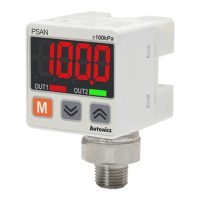
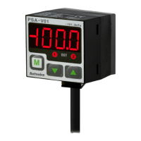
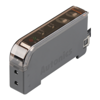
Unit Descriptions
1. Range of rating pressure:ItispossibletochangethepressureunitinPressure
sensor.Pleaseusedifferentunitaslabelforyourapplication.
2. 4digit LED display(Red):Usedtoindicatemeasuredpressurevalue,setting
valueanderrormessage.
3. Output1 indicator(Red):Output1isON,LEDwillbeON.
4. Output2 indicator(Green):Output2isON,LEDwillbeON.
5. key:UsedtoenterintoPreset/ParametersettingmodeandtosaveSetting
mode.
6. , key:Usedtosetparameterandpreset,peakvaluecheckmode,function
settingoroutputoperationmode.
+ key:Usedforzeropointadjustmentfunctionbypressing + keys
over1sec.simultaneouslyinRUNmode.
1
2
4
6
3
5
Load
Load
(Brown)+V
(Black)OUT1
(White)OUT2
12-24VDC
※
:Forvoltageoutputtypeonly.
1kΩ
Main circuit
(Blue)0V
(Orange)
Analogoutput
voltage/current
Over current
protection
circuit
Over current
protection
circuit
Load
Load
(Brown)+V
(Blue)0V
(Black)OUT1
(White)OUT2
(Orange)Hold/
Autoshiftinput
12-24VDC
Main circuit
Over current
protection
circuit
Over current
protection
circuit
Load
Load
(Brown)+V
(Blue)0V
(Black)OUT1
(White)OUT2
(Orange)Hold/
Autoshiftinput
12-24VDC
Main circuit
Over current
protection
circuit
Over current
protection
circuit
1. Use the unit within the rated specications.
Failuretofollowthisinstructionmayresultinreorproductdamage.
2. Use dry cloth to clean the unit, and do not use water or organic solvent.
Failuretofollowthisinstructionmayresultinre.
3. This product is designed to detect the pressure of noncorrosive gas. Do not use for corrosive gas.
Failuretofollowthisinstructionmayresultinproductdamage.
4. Do not use the unit in the place where ammable/explosive/corrosive gas, humidity, direct sunlight,
radiant heat, vibration, impact, or salinity may be present.
Failuretofollowthisinstructionmayresultinreorexplosion.
5. Keep metal chip, dust, and wire residue from owing into the unit.
Failuretofollowthisinstructionmayresultinreorproductdamage.
※
The above specications are subject to change and some models may be discontinued without notice.
※
Be sure to follow cautions written in the instruction manual and the technical descriptions
(catalog, homepage).
※
Ifshort-circuitthecontroloutputterminalorsupplycurrentovertheratedspecification,normalcontrol
signalisnotoutputduetotheoutputshortovercurrentprotectioncircuit
6.Donotpullthecablewithatensilestrengthof30Norover.
Cautions during Use
1.Followinstructionsin'CautionsduringUse'.
Otherwise,Itmaycauseunexpectedaccidents.
2.12-24VDCpowersupplyshouldbeinsulatedandlimitedvoltage/currentorClass2,SELVpowersupplydevice.
3.Usetheproduct,3secaftersupplyingpower.
4.Whenusingswitchingmodepowersupply,frameground(F.G.)terminalofpowersupplyshouldbegrounded.
5.Wireasshortaspossibleandkeepawayfromhighvoltagelinesorpowerlines,topreventinductivenoise.
6.Thisunitmaybeusedinthefollowingenvironments.
①
Indoors(intheenvironmentconditionratedin'Specications')
②
Altitudemax.2,000m
③
Pollutiondegree3
④
Installation category II
Photoelectric Sensors TemperatureControllers
FiberOpticSensors Temperature/HumidityTransducers
Door Sensors SSRs/PowerControllers
DoorSideSensors Counters
Area Sensors Timers
Proximity Sensors Panel Meters
Pressure Sensors Tachometer/Pulse(Rate)Meters
RotaryEncoders DisplayUnits
Connector/Sockets Sensor Controllers
SwitchingModePowerSupplies
ControlSwitches/Lamps/Buzzers
I/OTerminalBlocks&Cables
StepperMotors/Drivers/MotionControllers
Graphic/LogicPanels
FieldNetworkDevices
LaserMarkingSystem(Fiber,CO
₂
,Nd:YAG)
LaserWelding/CuttingSystem
http://www.autonics.com
HEADQUARTERS:
18,Bansong-ro513beon-gil,Haeundae-gu,Busan,
SouthKorea,48002
TEL:82-51-519-3232
E-mail:sales@autonics.com
DRW171185A A
DRW171185A A