Parameter Groups
● Parameter Group 1
● Parameter Group 2
Alarm [
AL-1
/
AL-2
] Input Correction [
IN-B
]
Input Digital Filter [
MAvF
]
Hysteresis [
HYS
]
Manual Reset [
REST
]
Digital Input Key ( + 3sec.) [
DI-K
]
Control Output MV When Input Sensor Line Is Broken [
ErMV
]
Parameter Lock [
LOC
]
Error
Cautions during Use
Controller itself does not have errors but there may be error by external input temperature sensor. This function
is for correcting this error.
E.g.) If actual temperature is 80
℃
but controller displays 78
℃
, set input correction value [
IN-B
] as '
002
' and
controller displays 80
℃
.
※
As the result of input correction, if current temperature value (PV) is over each temperature range of input
sensor, it displays '
HHHH
' or '
LLLL
'.
If current temperature (PV) is uctuating repeatedly by rapid change of input signal, it re ects to MV and stable
control is impossible. Therefore, digital lter function stabilizes current temperature value.
For example, set input digital lter value as 0.4 sec, and it applies digital lter to input values during 0.4 sec and
displays this values. Current temperature may be different by actual input value.
The function to set control output MV in case of open error. Users are able to set by ON/OFF setting or MV
setting. It executes control output by set MV regardless of ON/OFF or PID control output.
● If Hysteresis is too narrow, hunting (oscillation,
chattering) could occur due to external noise.
● In case of ON / OFF control mode, even if PV reaches
stable status, there still occurs hunting. It could be due
to Hysteresis [
HYS
] SV, load’s response characteristics
or sensor’s location. In order to reduce hunting to a
minimum, it is required to take into following factors
consideration when designing temp. controlling;
proper Hysteresis [
HYS
], heater’s capacity, thermal
characteristics, sensor’s response and location.
When selecting P/PD control mode, certain temperature difference
exists even after PV reaches stable status because heater's rising
and falling time is inconsistent due to thermal characteristics of
controlled objects, such as heat capacity, heater capacity. This
temperature difference is called offset and manual reset [
REST
]
function is to set/correct offset.
When PV and SV are equal, reset value is 50.0%. After control
is stable, PV is lower than SV, reset value is over 50.0% or PV is
higher than SV, reset value is below 50.0%.
Set below 50.0 as reset value
Set over 50.0 as reset value
Offset
Offset
SV
●Manual reset [
REST
] by control result
Heating operation
Hysteresis
[
HYS
]
ON OFF
SV
Control
output
Temp.
AM!A
Alarm
operation
Alarm
option
3)Sensor break alarm
The function that alarm output will be ON when sensor is not connected or when sensor's disconnection is
detected during temperature controlling. You can check whether the sensor is connected with buzzer or other
units using alarm output contact. It is selectable between standard alarm [
SBaA
] or alarm latch [
SBaB
].
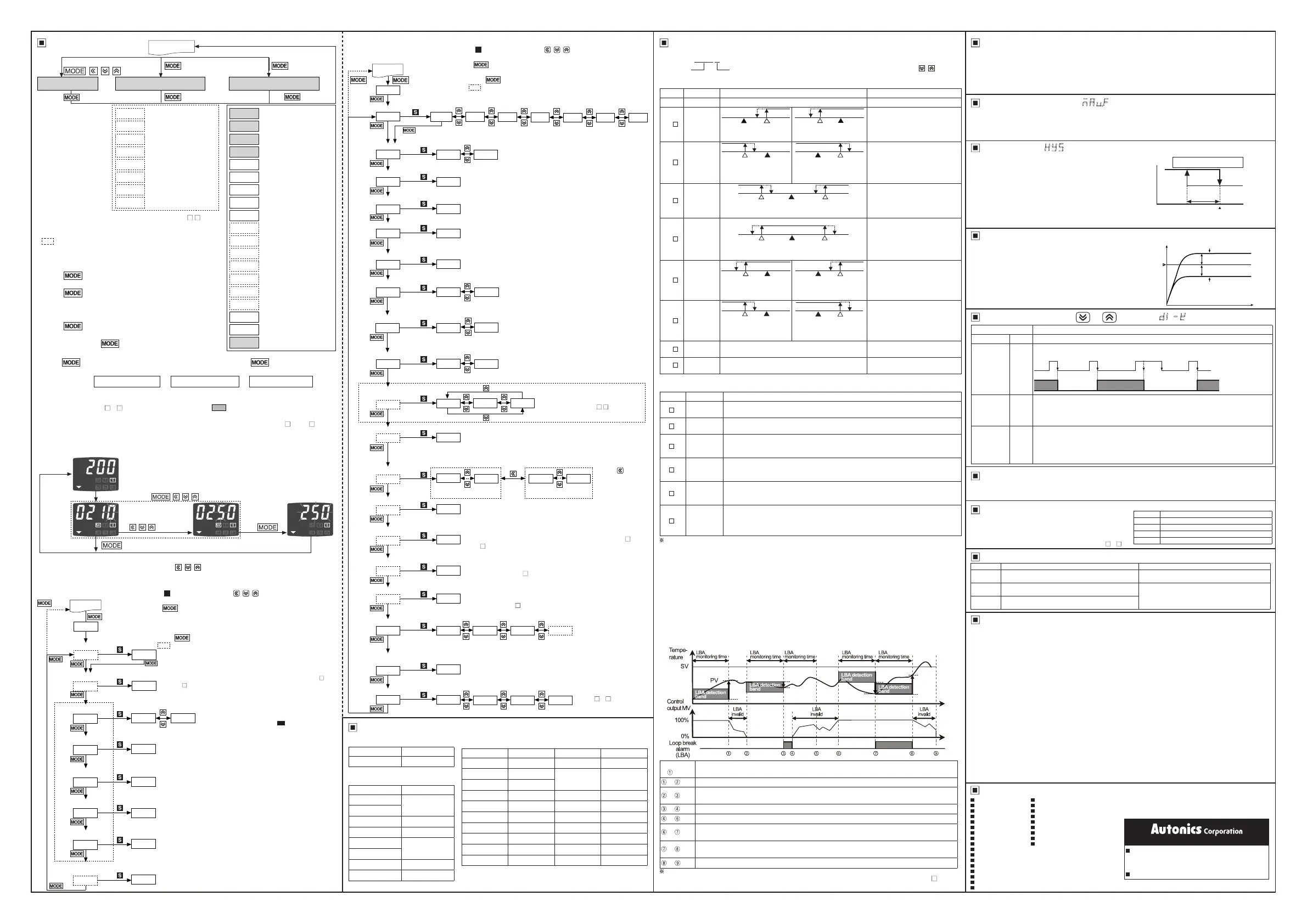
4)Loop break alarm (LBA)
It checks control loop and outputs alarm by temperature change of the subject. For heating control (cooling
control), when control output MV is 100% (0% for cooling control) and PV is not increased over than LBA
detection band [
LBaB
] during LBA monitoring time [
LBaT
], or when control output MV is 0% (100% for cooling
control) and PV is not decreased below than LBA detection band
[
LBaB
] during LBA monitoring time [
LBaT
], alarm output turns ON.
Start control
to
When control output MV is 100%, PV is increased over than LBA detection band [
LBaB
] during
LBA monitoring time [
LBaT
].
to
The status of changing control output MV (LBA monitoring time is reset.)
to
When control output MV is 0% and PV is not decreased below than LBA detection band [
LBaB
]
during LBA monitoring time [
LBaT
], loop break alarm (LBA) turns ON after LBA monitoring time.
to
Control output MV is 0% and loop break alarm (LBA) turns and maintains ON.
to
The status of changing control output MV (LBA monitoring time is reset.)
to
When control output MV is 100% and PV is not increased over than LBA detection band [
LBaB
]
during LBA monitoring time [
LBaT
], loop break alarm (LBA) turns ON after LBA monitoring time.
to
When control output MV is 100% and PV is increased over than LBA detection band [
LBaB
]
during LBA monitoring time [
LBaT
], loop break alarm (LBA) turns OFF after LBA monitoring time.
to
The status of changing control output MV (LBA monitoring time is reset.)
2)Alarm opetion
Option Name Description
ㅁㅁㅁㅁㅁㅁAM .A
Standard
alarm
If it is an alarm condition, alarm output is ON. If it is a clear alarm condition, alarm output
is OFF.
AM ㅁ.ㅁㅁㅁㅁㅁㅁㅁㅁㅁㅁB
Alarm latch
If it is an alarm condition, alarm output is ON and maintains ON status.
(Alarm output HOLD)
AM .C
Standby
sequence 1
First alarm condition is ignored and from second alarm condition, standard alarm
operates. When power is supplied and it is an alarm condition, this rst alarm condition
is ignored and from the second alarm condition, standard alarm operates.
AM .D
Alarm latch
and standby
sequence 1
If it is an alarm condition, it operates both alarm latch and standby sequence. When
power is supplied and it is an alarm condition, this rst alarm condition is ignored and
from the second alarm condition, alarm latch operates.
AM .E
Standby
sequence 2
First alarm condition is ignored and from second alarm condition, standard alarm
operates. When re-applied standby sequence and if it is alarm condition, alarm output
does not turn ON. After clearing alarm condition, standard alarm operates.
AM .F
Alarm latch
and standby
sequence 2
Basic operation is same as alarm latch and standby sequence1. It operates not only by
power ON/OFF, but also alarm setting value, or alarm option changing. When re-applied
standby sequence and if it is alarm condition, alarm output does not turn ON. After
clearing alarm condition, alarm latch operates.
1)Alarm operation
When executing auto-tuning, LBA detection band[
LBaB
] and LBA monitoring time are automatically set based
on auto tuning value. When alarm operation mode [
AL-1
,
AL-2
] is set as loop break alarm (LBA)[
LBa
], LBA
detection band [
LBaB
] and LBA monitoring time [
LBaT
] parameter is displayed.
Condition of re-applied standby sequence for standby sequence 1, alarm latch and standby sequence 1: Power ON
Condition of re-applied standby sequence for standby sequence 2, alarm latch and standby sequence 2: Power ON,
changing set temperature, alarm temperature [
AL1
,
AL2
] or alarm operation [
AL-1
,
AL-2
], switching STOP mode
to RUN mode.
Mode Name Alarm operation Description
AM)_
- -
No alarm output
AM!
Deviation
high-limit
alarm
SV
100℃
PV
110℃
OFF ONH
PV
90℃
SV
100℃
OFF ONH
If deviation between PV and SV
as high-limit is higher than set
value of deviation temperature,
the alarm output will be ON.
High deviation: Set as 10℃ High deviation: Set as -10℃
AM@
Deviation
low-limit
alarm
PV
90℃
SV
100℃
OFFON H
SV
100℃
PV
110℃
OFFON H
If deviation between PV and SV
as low-limit is higher than set
value of deviation temperature,
the alarm output will be ON.
Lower deviation: Set as
10℃
Lower deviation: Set as
-10℃
AM#
Deviation
high/low-
limit
alarm
PV
90℃
PV
110℃
SV
100℃
OFFON ONH H
If deviation between PV and SV
as high/low-limit is higher than set
value of deviation temperature,
the alarm output will be ON.
High/Lower deviation: Set as 10℃
AM$
Deviation
high/low-
limit
reserve
alarm
If deviation between PV and SV
as high/low-limit is higher than set
value of deviation temperature,
the alarm output will be OFF.
PV
90℃
PV
110℃
SV
100℃
OFF OFFONH H
High/Lower deviation: Set as 10℃
AM%
Absolute
value high
limit alarm
PV
90℃
SV
100℃
OFF ONH
SV
100℃
PV
110℃
OFF ONH
If PV is higher than the absolute
value, the output will be ON.
Absolute-value Alarm:
Set as 90℃
Absolute-value Alarm:
Set as 110℃
AM^
Absolute
value low
limit alarm
PV
90℃
SV
100℃
OFFON H
SV
100℃
PV
110℃
OFFON H
If PV is lower than the absolute
value, the output will be ON.
Absolute-value Alarm:
Set as 90℃
Absolute-value Alarm:
Set as 110℃
SBa
Sensor
break alarm
-
It will be ON when it detects
sensor disconnection.
LBa
Loop break
alarm
-
It will be ON when it detects loop
break.
※
H: Alarm output hysteresis[
AHYS
]
Setting range: Deviation alarm (-[F.S] to [F.S],
Absolute value alarm (temperature range)
※
In case alarm operation mode [
AL-1
,
AL-2
],
AM)_
/
SBa
/
LBa
of Parameter group 2 is set to [
AL-1
,
AL-2
], no
parameters is displayed.
Setting range: 0.1 to 999.9
℃/℉
ON/OFFcontrol
hysteresis
Manual reset
Derivation time
Integral time
Proportional band
Auto-tuning
※
1
AL1 alarm temperature
AL2 alarm temperature
Setting range: 0 to 9999 sec.
※
Integral operation will be OFF when set value is "0".
Setting range: 0 to 9999 sec.
※
Derivative operation will be OFF when set value is "0".
Setting range: 0.0 to 100.0%
※
It is displayed in P/PD control.
Setting range: 1 to 100
℃/℉
(For
DPtL
/
CUsL
: 0.1 to 50.0
℃/℉)
※
It is displayed when control type parameter [
C-MD
] of Parameter
group 2 is set
ONOF
.
※
It starts to operate auto-tuning when it is ON and
set as OFF automatically after finish the operation.
※
Deviation indicators
(
▲, , ▼
) flash (cycle:1
sec.) during auto tuning function.
AL1
AL2
AT
P
I
PAR1
D
REST
ONOFF
01)0
0000
0000
05)0
002
HYS
3 sec.
2 sec.
Run mode
※
2
※
3
1250
1250
※
AC/DC power type has no SSR drive output method [
SSrM
] and
supports only ON/OFF output when selecting
SSR
in control output
[
OUT
].
Parameter Factory default Parameter Factory default
IN-T ㅁKCA T 02)0
UNIT ?C
AL-1 AM!A
IN-B 0000
MAvF 00)1 AL-2 AM@A
L-SV -050 AHYS 0001
H-SV 1200 LBaT 0000
O-FT HEAT LBaB 002
C-MD PID DI-K STOP
OUT RLY ErMV 00)0
SSrM STND LOC OFF
●
SV setting
●
Parameter Group 1
●
Parameter Group 2
Parameter Factory default
-
0
Parameter Factory default
AL1
1250
AL2
AT OFF
P 01)0
I
0000
D
REST 05)0
HYS 002
Factory Default
Display Description
OFF
Unlock
LOC1
Lock parameter group 2
LOC2
Lock parameter group 1, 2
LOC3
Lock parameter group 1, 2, SV setting
A function to prevent changing SV and parameters of
each setting group. Parameter setting values are still
possible to check when parameter lock is set.
※
OFF
,
LOC1
are available only for indicator (TC4 -N N).
Display Description Troubleshooting
OPEN
Flashes if input sensor is disconnected or sensor
is not connected.
Check input sensor state.
HHHH
Flashes if measured sensor input is higher than
temperature range. When input is within the rated temperature
range, this display disappears.
LLLL
Flashes if measured sensor input is lower than
temperature range.
Major Products
Press any key among
, , , .
※
1: It is not displayed for AC/DC power model (TC4 - 2R).
※
If no key entered for 30 sec., it returns to RUN mode
automatically and the set value of parameter is not be saved.
※
This parameter might not be displayed depending on
other parameter settings.
SV setting Parameter group 1[
PAR1
] Parameter group 2[
PAR2
]
4sec.
2sec.
3sec.
3sec.
②①
④
③
⑤
RUN mode
AL1
AL2
AT
Pㅁㅁ
I
D
REST
HYS
AL1 alarm temperature
AL2 alarm temperature
Auto tuning
Proportional band
Integral time
Derivative time
Manual reset (Normal
deviation correction)
ON/OFF
control hysteresis
IN-Tㅁㅁ
UNITㅁㅁ
IN-Bㅁㅁ
MAvFㅁㅁ
L-SV
H-SV
O-FTㅁㅁ
C-MD
OUTㅁㅁ
SSrMㅁㅁ
T
AL-1ㅁㅁ
AL-2ㅁㅁ
AHYSㅁㅁ
LBaTㅁㅁ
LBaBㅁㅁ
DI-Kㅁㅁ
ErMVㅁㅁ
LOCㅁㅁ
Input type
Temperature unit
Input correction
Input digital lter
SV low-limit value
SV high-limit value
Control output operation
Control type
Control output
SSR drive output method
※
1
Control cycle
AL1
alarm operation mode
AL2
alarm operation mode
Alarm output hysteresis
LBA
monitoring time
LBA
detection range
Digital input key
Control output MV in case
of input break error
Parameter lock
①
Press any key once in RUN mode, it advances to set value
setting group.
②
Press key over 2sec. in RUN mode, it advances to
parameter group 1.
③
Press key over 4sec. in RUN mode, it advances to
Parameter group 2.
④
First parameter will be displayed on viewer when it
advances to the setting group.
⑤
Press key over 3sec. in the setting group, it returns
to RUN mode.
※
Exception: Press key once in SV setting group it
returns to RUN mode.
※
Press key again within a sec after return to RUN mode by press key over 3sec., it
advances to the first parameter of previous setting group.
※
Parameter setup
Parameter group 2
→
Parameter group 1
→
SV setting
• Set parameter as the above considering parameter relation of each setting group.
• Check parameter set value after change parameter of Parameter group 2.
※
Indicator model (TC4 -N N)displays shaded parameter ( ) of Parameter group 2.
※
AL-1
,
AL-2
parameters of Parameter group 2 is decided whether to display according by alarm output type.
※
If alarm operation mode[
AL-1
,
AL-2
] of Parameter group 2 is set to
AM)_
/
SBa
/
LBa
,
AHYS
parameter is not displayed.
● Flow Chart For SV Setting Group
Change set value
by , , keys.
Press any key among , , , .
①RUN mode (display current temperature)
②Set value change mode
③Finish the setup.
④Check SV
※
In case of changing set temperature from 210
℃
to 250
℃
※
1:
S
: Press any key among , , .
※
2: After checking/changing set value at each parameter, and press
key, set value flashes twice and it moves to next parameter
automatically.
※
3: It is displayed when control type parameter [
C-MD
] of parameter
group 2 is set
PID
.
※
Press key for 3 sec. to return RUN mode at any parameter.
※
This parameter might not be displayed depending on other
parameter settings.
※
1:
S
: Press any key among , , .
※
2: After checking/changing set value at each parameter, and press
key, set value flashes twice and it moves to next parameter
automatically.
※
Press key for 3 sec. to return RUN mode at any parameter.
※
This parameter might not be displayed depending on other
parameter settings.
Parameter lock
Control output MV in case
of input break error
Digital input key
LBA detection band
LBA monitoring time
Alarm output hysteresis
AL2 alarm operation
AL1 alarm operation
Control cycle
※
Alarm operation mode
※
Alarm option
SSR drive
output method
Control output
Control type
Control output operation
SV low-limit value
SV high-limit value
Input digital lter
Input correction
Temperature unit
Input type
3 sec.
4 sec.
Run mode
※
Front temperature unit indicator will flash when
selecting the unit.
※
When changing temperature unit, SV,
IN-B
,
H-SV
,
L-SV
,
AL1
,
AL2
,
LBaT
,
LBaB
,
AHYS
parameters
are initialized.
※
When changing input type, SV,
IN-B
,
H-SV
,
L-SV
,
AL1
,
AL2
,
LBaT
,
LBaB
,
AHYS
parameters are initialized.
Setting range: -999 to 999 (
DPtL
/
CUsL
: -199.9 to 999.9)
※
Operates only selected output between Relay or SSR.
※
When changing control output operation,
ErMU
is
initialized.
※
When changing control type,
ErMU
is initialized
(control output MV is below 100%) and
DI-K
turns
OFF automatically.
※
Same with the above [
AL-1
].
※
When changing alarm operation AL1, AL2, alarm temperature of
AL1, AL2 is initialized.
※
Press key to
convert alarm
operation mode
into alarm option.
Setting range: 0.1 to 120.0 sec.
※
Set input digital filter time for average input value affected control,
and display value.
Setting range: Within the rated temperature
range by input sensor [
L-SV
≤ (
H-SV
-1digit)]
When changing SV low-limit value,
if SV <
L-SV
, SV is initialized as
L-SV
.
Setting range: Within the rated temperature
range by input sensor [
H-SV
≥ (
L-SV
+1digit)]
When changing SV high-limit value,
if SV >
H-SV
, SV is initialized as
H-SV
.
Setting range:0.5 to 120.0 sec.
※
If control output [
OUT
] is set as
RLY
, factory default is 20.0 sec, or
set as
SSR
, factory default is 2.0 sec.
※
This
T
will not be displayed when SSR drive output method [
SSrM
]
is set as
CYCL
,
PHAS
.
Setting range: 1 to 100
℃/℉
(
DPtL
/
CYsL
: 0.1 to 50.0
℃
)
※
If alarm operation mode [
AL-1
,
AL-2
] is set to
AM)_
,
SBa
,
LBA
,
AHYS
parameter is not displayed.
Setting range: 0 to 9999sec. (Automatically setting with Auto-tunning)
※
LBaT
parameter is displayed when alarm operation mode [
AL-1
,
AL-2
] is set as
LBA
.
Setting range: 0.0 to 100.0%
※
0.0/100.0% is displayed when control type parameter [
C-MD
] is
set
ONOF
.
※
When changing PID control to ON/OFF control, if MV is below
100.0%, it is initialized as 0.0%.
※
For indicator model
(TC4 -N N), only
OFF
,
LOC1
are available.
※
AlRE
is not displayed for not alarm output model.
※
AT
is not displayed
when control type parameter [
C-MD
] is set
ONOF
.
Setting range: 0 to 999
℃/℉
(
DPtL
/
CUs
: 0.0 to 999.9
℃/℉
)
(Automatically setting with Auto-tunning)
※
When alarm operation mode [
AL-1
,
AL-2
] is set as loop break
alarm (LBA) [
LBA
], and
LBaT
parameter does not set as 0,
LBaB
parameter is displayed.
※
It is displayed when selecting control
output [
OUT
] as
SSR
. For AC/
DC power type (TC4 - 2R), this
parameter [
SSrM
] is not displayed.
PAR2
IN-T
UNIT
IN-Bㅁㅁ
MAvF
L-SV
H-SV
O-FT
C-MD
OUT
SSrM
T
AL-1
AL-2
AHYS
LBaT
LBaB
DI-K
ErMV
LOC
LBaA
AM!Aㅁ AM!B
?F?C
000
)1
-050
1200
HEAT
PID
RLY
STND
02)0
AM!A
AM@A
001
0
002
00)0
SSR
ONOF
COOL
CYCL PHAS
※
2
※
1
KCA JIC
LIC
DPtH
DPtL
CU%H CU%L
STOP AlRE ATOFF
LOC1 LOC2 LOC3
OFF
Ti
※In case of [
IN-T
]
input sensor type,
low/high-limit setting
temperature (SV) is
also set as max./min.
temperature range of
input sensor.
Set both alarm operation and alarm option by combining.
Each alarm operates individually in two alarm output models.
When the current temperature is out of alarm range, alarm
clears automatically. If alarm option is alarm latch or alarm latch
and standby sequence 1/2, press digital input key( + 3 sec.,
digital input key[
DI-K
] of Parameter group 2 set as
AlRE
), or
turn OFF the power and turn ON to clear alarm.
Parameter
Operation
OFF
OFF
It does not use digital input key function.
RUN/STOP
STOP
Pauses control output. Auxiliary output (except loop break alarm, sensor break alarm)
except Control output operates as setting. Hold the digital input keys for 3 sec. to restart.
RUN RUN
t t tt
STOP STOP RUN
Digital input key
(t: over 3 sec.)
Clear alarm
AlRE
Clears alarm output by force.
(only when alarm option is alarm latch, or alarm latch and standby sequence 1/2 .)
This function is applied when present value is out of alarm operation range but alarm
output is ON. Alarm operates normally right after clearing alarm.
Auto-tuning
AT
Starts/Stops auto-tuning. This function is same as auto-tuning[
AT
] of parameter group 1.
(You can start auto-tuning [
AT
] of parameter group 1 and stop it by digital input key.)
※
This parameter
AT
appears only when control method [
C-MD
] Parameter group 2
is set as
PID
. When control method [
C-MD
] Parameter group 2 is set as
ONOF
, this
parameter is changed as
OFF
.
Reset all parameters as factory default. Hold the front + +
keys for 5 sec., to enter parameter reset [
INIT
]
parameter. Select '
YES
' and all parameters are reset as factory default. Select ‘
NO
’ and previous settings are
maintained. If setting parameter lock [
LOC
] or processing auto-tuning, parameter reset is unavailable.
● Parameter Reset
http://www.autonics.com
HEADQUARTERS:
18, Bansong-ro 513beon-gil, Haeundae-gu, Busan,
South Korea, 48002
TEL: 82-51-519-3232
E-mail:
sales@autonics.com
DRW170775AA
Photoelectric Sensors Temperature Controllers
Fiber Optic Sensors Temperature/Humidity Transducers
Door Sensors SSRs/Power Controllers
Door Side Sensors Counters
Area Sensors Timers
Proximity Sensors Panel Meters
Pressure Sensors Tachometer/Pulse (Rate) Meters
Rotary Encoders Display Units
Connector/Sockets Sensor Controllers
Switching Mode Power Supplies
Control Switches/Lamps/Buzzers
I/O Terminal Blocks & Cables
Stepper Motors/Drivers/Motion Controllers
Graphic/Logic Panels
Field Network Devices
Laser Marking System (Fiber, Co
₂
, Nd: YAG)
Laser Welding/Cutting System
1. Follow instructions in 'Cautions during Use'. Otherwise, It may cause unexpected accidents.
2. Check the polarity of the terminals before wiring the temperature sensor.
For RTD temperature sensor, wire it as 3-wire type, using cables in same thickness and length.
For thermocouple (CT) temperature sensor, use the designated compensation wire for extending wire.
3. Keep away from high voltage lines or power lines to prevent inductive noise.
In case installing power line and input signal line closely, use line lter or varistor at power line and shielded
wire at input signal line.
Do not use near the equipment which generates strong magnetic force or high frequency noise.
4.
Install a power switch or circuit breaker in the easily accessible place for supplying or disconnecting the power.
5. Do not use the unit for other purpose (e.g. voltmeter, ammeter), but temperature controller.
6. When changing the input sensor, turn off the power rst before changing.
After changing the input sensor, modify the value of the corresponding parameter.
7. 24VAC, 24-48VDC power supply should be insulated and limited voltage/current or Class 2, SELV power
supply device.
8. Make a required space around the unit for radiation of heat.
For accurate temperature measurement, warm up the unit over 20 min after turning on the power.
9. Make sure that power supply voltage reaches to the rated voltage within 2 sec after supplying power.
10. Do not wire to terminals which are not used.
11. This unit may be used in the following environments.
①
Indoors (in the environment condition rated in 'Specications')
②
Altitude max. 2,000m
③
Pollution degree 2
④
Installation category II
 Loading...