I N S T R U C T I O N M A N U A L
※
1: The weight includes packaging. The weight in parenthesis is for unit only.
※Environment resistance is rated at no freezing or condensation.
Ordering Information
Specications
TZ 4 SP 1 4 R
Item
Digit
Size
Option output
Power supply
Control
output
R
Relay output
S
SSR drive output
C
Current output
4
100-240VAC 50/60Hz
1
※
1,
※
2
Event 1
2
※
2
Event 1 + Event 2
R
※
2
Event 1 + PV transmission (DC4-20mA)
T
Event 1 + RS485 communication
A
Event 1 + Event 2 + PV transmission (DC4-20mA)
B
Event 1 + Event 2 + RS485 communication
SP
DIN W48×H48mm (plug type)
※
3
ST
DIN W48×H48mm (terminal block type)
M
DIN W72×H72mm
W
DIN W96×H48mm
H
DIN W48×H96mm
L
DIN W96×H96mm
4
9999 (4-digit)
TZ
Temperature controller
※
Theunitcannotbeconguredwithanyrandomcombinationfromtheaboveorderinginformation.Please
refer to Specicationsforpossiblecongurations.
※
1: TZ4SP only supports Event 1 option output.
※
2: TZ4ST only supports Event 1, Event 1 + Event 2, and Event 1 + PV transmission (DC4-20mA) option
output.
※
3: 11-pin sockets (PG-11, PS-11(N)) are sold separately.
Connections
Dual PID Control Temperature Controller
TZ SERIES
Dimensions
Input Type and Range
Input type Decimal point Display Input range (
℃
) Input range (
℉
)
Thermo
couple
K (CA) 1
KCaH
-100 to 1300 -148 to 2372
K (CA) 0.1
KCaL
-100.0 to 999.9 Not supported
J (IC) 1
JIcH
0 to 800 32 to 1472
J (IC) 0.1
JIcL
0.0 to 800.0 Not supported
R (PR) 1
R PR
0 to 1700 32 to 3092
E (CR) 1
ECrH
0 to 800 32 to 1472
E (CR) 0.1
ECrL
0.0 to 800.0 Not supported
T (CC) 1
TCcH
-200 to 400 -328 to 752
T (CC) 0.1
TCcL
-199.9 to 400.0 Not supported
S (PR) 1
S PR
0 to 1700 32 to 3092
N (NN) 1
NN
0 to 1300 32 to 2372
W (TT) 1
U TT
0 to 2300 32 to 4172
RTD
JPt100Ω 1
JPtH
0 to 500 32 to 932
JPt100Ω 0.1
JPtL
-199.9 to 199.9 -199.9 to 391.8
DPt100Ω 1
DPtH
0 to 500 32 to 932
DPt100Ω 0.1
DPtL
-199.9 to 199.9 -199.9 to 391.8
Analog
Voltage
0 - 10VDC
A--1
-1999 to 9999
(display range will vary depending on the
decimal point.)
1 - 5VDC
A--2
Current DC4 - 20mA
A--3
Conguring Input Type
Pleaseconguretheinternalswitchesbeforesupplyingpower.Aftersupplyingpower,configuretheinputtype
[
IN-T
] in parameter group 2 according to the input type.
Input type S/W 1 S/W 2
Thermocouple
1 1 mA V
RTD
Analog
Voltage
(0-10VDC,
1-5VDC)
2 2
mA V
Current
(DC4-20mA)
2 2
mA V
●Detachingthecase
Press the front case then pull the case to detach the case from the body.
Conguretheinternalswitchesasinputtype.
Series
TZ4SP TZ4ST TZ4M TZ4W TZ4H TZ4L
Power supply 100-240VAC 50/60Hz
Allowable voltage range 90 to 110% of rated power voltage
Power consumption
Max. 5VA (100-240VAC 50/60Hz)
Max. 6VA (100-240VAC 50/60Hz)
Display method 7-segment LED (PV: red, SV: green)
Character
size
PV (W×H)
4.8×7.8mm
9.8×14.2mm
8.0×10.0mm 3.8×7.6mm
9.8×14.2mm
SV (W×H) 8.0×10.0mm
8.0×10.0mm
Input
type
RTD DPt100Ω,JPt100Ω,3-wire (allowed resistance: max. 5Ωperline)
TC
K (CA), J (IC), R (PR), E (CR), T (CC), S (PR), N (NN), W (TT)
(allowed resistance: max. 100Ωperline)
Analog 1-5VDC , 0-10VDC , DC4-20mA
Display accuracy F.S. ±0.3% or 3
℃
, greater value
Control
output
Relay 250VAC 3A 1c
SSR Max. 12VDC ±3V 30mA
Current DC4-20mA (load resistance max. 600Ω)
Option
output
EVENT1 250VAC 1A 1a
EVENT2
-
250VAC 1A 1a
PV transmission
-
DC4-20mA (load resistance max. 600Ω)
Communication
-
RS485 communication
Control method ON/OFF, P, PI, PD, PIDF, PIDS control
Alarm output hysteresis 1 to 100
℃
(0.1 to 100.0
℃
) variable
Proportional band (P) 0.0 to 100.0%
Integral time (I) 0 to 3,600 sec
Derivative time (D) 0 to 3,600 sec
Control period (T) 1 to 120 sec
Sampling period 0.5 sec
LBA setting 1 to 999 sec
Ramp setting Ramp Up, Ramp Down: 1 to 99 min each
Dielectric strength 2,000VAC 50/60Hz for 1 min (between input and power terminals)
Vibration
Mechanical
0.75mm amplitude at frequency 10 to 55Hz (for 1 min) in each X, Y, Z direction for 2 hours
Electrical
0.5mm amplitude at frequency 10 to 55Hz (for 1 min) in each X, Y, Z direction for 10 min
Relay
life cycle
Control output
Mechanical: min. 10,000,000 operations,
Electrical: min. 100,000 operations (250VAC 3A resistance load)
Option output
Mechanical: min. 20,000,000 operations,
Electrical: min. 500,000 operations (250VAC 1A resistance load)
Insulation resistance Over 100MΩ(at 500VDC megger)
Noise immunity Square shaped noise by noise simulator (pulse width 1
㎲
) ±2kV R-phase, S-phase
Memory retention Approx. 10 years (non-volatile semiconductor memory type)
Environ-
ment
Ambient temp. -10 to 50
℃
, storage: -20 to 60
℃
Ambient humi. 35 to 85%RH, storage: 35 to 85%RH
Approval
Weight
※
1
Approx. 205g
(approx. 144g)
Approx. 218g
(approx. 162g)
Approx. 360g
(approx. 228g)
Approx. 365g
(approx. 246g)
Approx. 474g
(approx. 304g)
Thank you for choosing our Autonics product.
Please read the following safety considerations before use.
Safety Considerations
Warning
※
Please observe all safety considerations for safe and proper product operation to avoid hazards.
※
Safety considerations are categorized as follows.
Warning
Failure to follow these instructions may result in serious injury or death.
Caution
Failure to follow these instructions may result in personal injury or product damage.
※
The symbols used on the product and instruction manual represent the following
symbol represents caution due to special circumstances in which hazards may occur.
Caution
※
The above specications are subject to change and some model may be discontinued
without notice.
※
Be sure to follow cautions written in the instruction manual and the technical descriptions
(catalog, homepage).
(unit: mm)
(unit: mm)
●TZ4SP
MAIN OUT
SSR Current
-
+
9
10
V
12VDC ±3V
30mA Max.
-
+
9
10
mA
DC4-20mA
Load600ΩMax.
MAIN OUT
SSR Current
12VDC ±3V
30mA Max.
-
+
12
13
V
DC4-20mA
Load600ΩMax.
-
+
12
13
mA
●TZ4ST
●TZ4M
●TZ4L●TZ4H
●TZ4W
EV1 OUT
250VAC
1A 1a
SV2 IN
Max.5VDC
250
㎂
MAIN OUT
250VAC 3A 1c
Resistive load
SOURCE
100-240VAC 50/60Hz 5VA
H
C
L
-
-
+
+
B'
RTD
TC
SENSOR
B
A
-
+
5
2
10
9
8
1
11
4
3
7
6
MAIN OUT
SSR Current
12VDC ±3V
30mA Max.
-
+
13
12
V
DC4-20mA
Load600ΩMax.
-
+
mA
13
12
SV2 IN
Max.5VDC
250
㎂
MAIN OUT
250VAC 3A 1c
Resistive load
B'
RTD
TC
SENSOR
B
A
-
+
H
C
L
-
+
RS485(B-)
RS485(A+)
-
+
PV OUT
DC4-20mA
SOURCE
100-240VAC
50/60Hz 6VA
EV1 OUT
250VAC
1A 1a
EV2 OUT
250VAC
1A 1a
6
5
4
3
2
1
14 15 16
13
12
11
10
9
8
7
MAIN OUT
SSR Current
V
-
+
15
14
12VDC ±3V
30mA Max.
mA
-
+
15
14
DC4-20mA
Load600ΩMax.
MAIN OUT
SSR Current
V
-
+
15
14
12VDC ±3V
30mA Max.
mA
-
+
15
14
DC4-20mA
Load600ΩMax.
MAIN OUT
SSR Current
V
-
+
15
14
12VDC ±3V
30mA Max.
mA
-
+
15
14
DC4-20mA
Load600ΩMax.
EV1 OUT
250VAC 1A 1a
EV2 OUT
250VAC 1A 1a
SV2 IN
Max.5VDC
250
㎂
MAIN OUT
250VAC 3A 1c
Resistive load
B'
TC
RTD
SENSOR
B
A
-
+
H
C
L
-
+
8
7
6
5
4
3
2
1
17
16
15
14
13
12
11
10
9
SOURCE
100-240VAC 50/60Hz 6VA
RS485(B-)
RS485(A+)
-
+
PV OUT
DC4-20mA
SOURCE
100-240VAC
50/60Hz 6VA
EV1 OUT
250VAC
1A 1a
EV2 OUT
250VAC
1A 1a
SV2 IN
Max.5VDC
250
㎂
MAIN OUT
250VAC 3A 1c
Resistive load
B'
RTD
TC
SENSOR
B A
- +
H
C
L
- +
17 16 15 14 13 12 11 10 9
8 7 6 5 4 3 2 1
PV OUT
DC4-20mA
-+
RS485
(A+)
RS485
(B-)
SOURCE
100-240VAC
50/60Hz 6VA
EV1 OUT
250VAC 1A 1a
EV2 OUT
250VAC 1A 1a
SV2 IN
Max.5VDC
250
㎂
MAIN OUT
250VAC 3A 1c
Resistive load
B'
TC
RTD
SENSOR
B
A
H
C
L
-
+
8
7
6
5
4
3
2
1
17
16
15
14
13
12
11
10
9
-
+
RS485(B-)
RS485(A+)
-
+
PV OUT
DC4-20mA
EV1 OUT
250VAC 1A 1a
SV2 IN
Max.5VDC
250
㎂
MAIN OUT
250VAC 3A 1c
Resistive load
PV OUT
DC4-20mA
EV2 OUT 250VAC 1A 1a
SOURCE
100-240VAC 50/60Hz 5VA
H
C
L
-
-
+
+
B'
RTD
TC
SENSOR
B
A
-
+
1
2
3
4
10
11
12
13
14
5
6
7
8
9
-
+
●TZ4SP ●TZ4ST
48
8.7
82.8
14.5
106
45
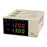
TEMPERATURE CONTROLLER
°C
PV
SV
EV1
OUT
AT
SV2
TZ4SP
TEMPERATURE CONTROLLER
EV2
98.8
107.5
45
8.7
48
TEMPERATURE CONTROLLER
°C
PV
SV
EV1
OUT
AT
SV2
TZ4ST
TEMPERATURE CONTROLLER
EV2
●TZ4M
72
13
90
10
67
113
TEMPERATURE CONTROLLER
TZ4M
SV2
AT
OUT
EV1
EV2
●TZ4H
TEMPERATURE CONTROLLER
TZ4H
SV2
AT
OUT
EV1
EV2
96
90
48
13
90
10
●TZ4W
96
13
90 10
45
48
TEMPERATURE CONTROLLER
TZ4W
AT
SV2
EV2
EV1
OUT
●TZ4L
SV2
AT
OUT
EV1
EV2
90
13
90 10
96
Panel cut-out dimensions
A
C
D
B
Size
Series
A B C D
TZ4SP Min. 55 Min. 62 45.5
+0.5
0
45.5
+0.5
0
TZ4ST Min. 55 Min. 62 45.5
+0.5
0
45.5
+0.5
0
TZ4M Min. 74 Min. 91 68.5
+0.5
0
68.5
+0.5
0
TZ4W Min. 112 Min. 50 92
+0.8
0
45.5
+0.6
0
TZ4H Min. 50 Min. 102 45
+0.6
0
92
+0.8
0
TZ4L Min. 98 Min. 106 91
+0.5
0
91
+0.5
0
TZ4ST, TZ4SP Series
48
61
45.4
61
3.9
7.4
15
4.5
4.2
41
12.2
47.8
Bracket
10
3.5
TZ4L, TZ4M, TZ4H, TZ4W Series
12
10
4
73
30
DRW170713AA
1. Fail-safe device must be installed when using the unit with machinery that may cause serious injury
or substantial economic loss. (e.g. nuclear power control, medical equipment, ships, vehicles,
railways, aircraft, combustion apparatus, safety equipment, crime/disaster prevention devices, etc.)
Failuretofollowthisinstructionmayresultinre,personalinjury,oreconomicloss.
2. Install on a device panel to use.
Failure to follow this instruction may result in electric shock.
3. Do not connect, repair, or inspect the unit while connected to a power source.
Failuretofollowthisinstructionmayresultinelectricshockorre.
4. Check 'Connections' before wiring.
Failuretofollowthisinstructionmayresultinre.
5. Do not disassemble or modify the unit.
Failuretofollowthisinstructionmayresultinelectricshockorre.
1. When connecting the power input and relay output, use AWG 20(0.50mm
2
) cable or over and tighten
the terminal screw with a tightening torque of 1.0N
.
m.
When connecting the sensor input and communication cable without dedicated cable, use AWG
28~16 cable or over and tighten the terminal screw with a tightening torque of 1.0N
.
m.
Failuretofollowthisinstructionmayresultinreormalfunctionduetocontactfailure.
2. Use the unit within the rated specications.
Failuretofollowthisinstructionmayresultinreorproductdamage.
3. Use dry cloth to clean the unit, and do not use water or organic solvent.
Failuretofollowthisinstructionmayresultinelectricshockorre.
4. Do not use the unit in the place where ammable/explosive/corrosive gas, humidity, direct sunlight,
radiant heat, vibration, impact, or salinity may be present.
Failuretofollowthisinstructionmayresultinreorexplosion.
5. Keep metal chip, dust, and wire residue from owing into the unit.
Failuretofollowthisinstructionmayresultinreorproductdamage.
a
b
<Round>
a
b
<Forked>
a Min. 3.5mm Min. 3.5mm
b Max. 7.2mm Max. 7.2mm
※
Useteminalsofsizespeciedbelow.