12
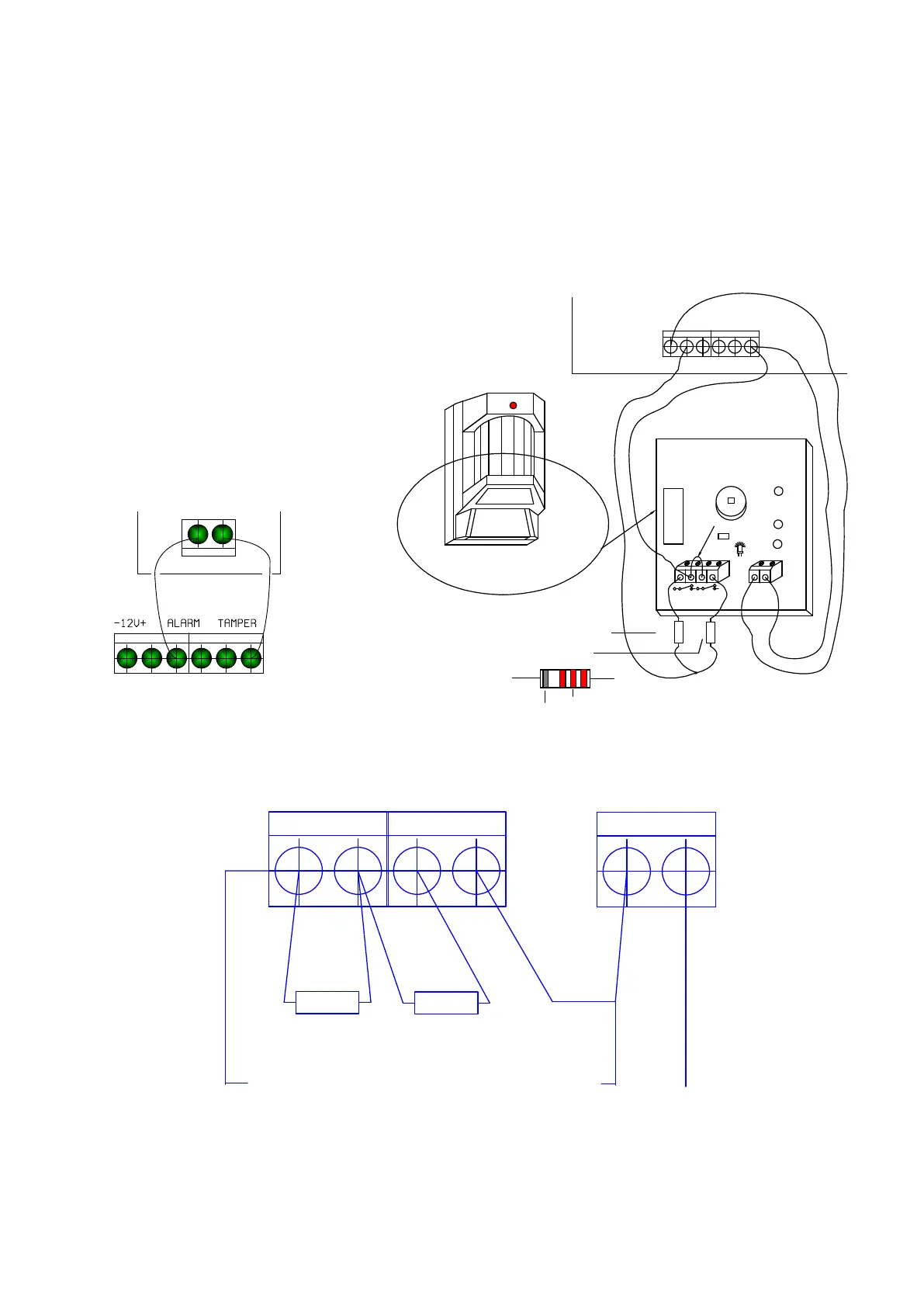
Use sensors with two separate switches or relay contacts; one for Alarm and one for Tamper. Each
contact should be connected to a different E.O.L. resistor. The Eye-Spy II sensors include the EOL
resistors on board, provide fast and convenient wiring, refer to figure 1A.
Alarm contacts connected in series with a 2.2K resistor; tamper contacts with a 4.7K resistor. Both
resistors are supplied with each system.
For Double-Pole wiring, connect the two resistors (use the ALARM ‘C’ and ‘NC’ contacts) to Alarm
and Tamper as shown in the following drawing:
PIR WITH TAMPER SWITCH
TAMPER ALARM
+ 12V -
4.7K 2.2K
1 2 3 4
+12V
-V
CONTROL PANEL
-V
Zone & Aux. Power Connection
Common -V
Tamper Resistor
Alarm Resistor
NC C POWER
RED
RED
RED
Silver
12V
Figure 1A: EYS II connected to Series 2000 Figure 1: Double-Pole wiring drawing
TamperAlarm
Power
Zone Input
Zone Common
1.5K Ohm
1.5K Ohm
N.C. C
N.C. C
-V +V
+12V
PIR Sensors wires Terminal
Figure 1A: European Double-Pole wiring drawing
Some countries are used to different double-pole wiring as shown in figure 1A. For this wiring please
follow the drawing below. This wiring way requires 1.5K resistors (1.5K resistors not supplied).
Control Panel
Z1 -V
Eye-Spy II