13
1.3 Keypad Wiring
Up to three AV-701TS/TI, five AV-702, or five AV-707/706 Keypads can be connected to
AV-2005/8 Control Panels. AV-707, AV-706 operates only with ‘PRO’ suffix panels.
LCD keypad (AV-707, AV-706) cannot be connected in same system with AV-701 or AV-702.
When using few keypads connect them in parallel (figure 2A). Don’t connect the keypad under
power. Each keypad contains four wires:
Red (+) Power, connect to + Aux. Power Orange System Data, connect to OR
Black (-) Power, connect to - Aux. Power Yellow System Strobe, connect to YE
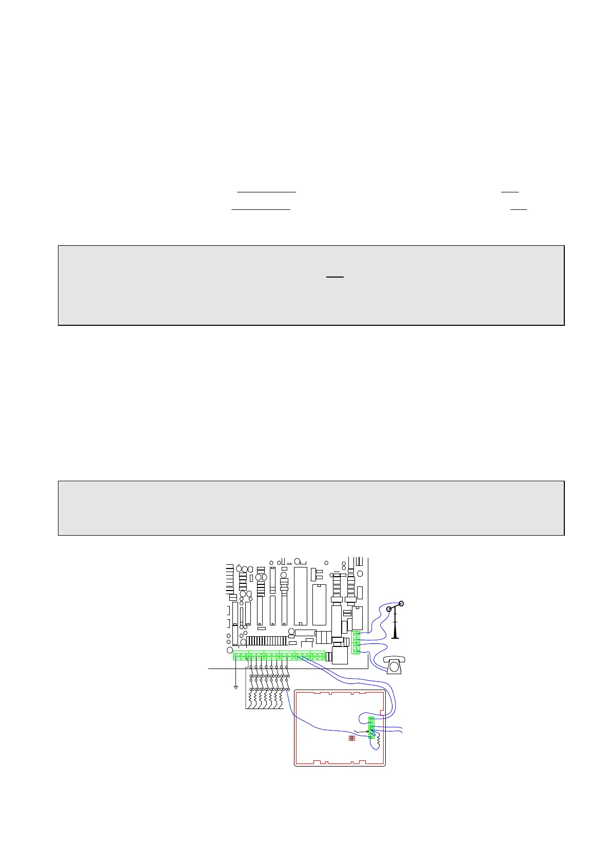
For proper connection, refer to wiring diagrams, figures 2 and 9 (9 is at the end of the manual).
IMPORTANT! Never run Keypad wires alongside telephone wires, high voltage wires, or
transmitting antennae. Separate keypad wires, not run in same cable with other devices
(telephone, sensors etc.). Do not use the keypad wires for supplying power to sensors or other
devices. Keypads have no polarity protection; verify the 12V power polarity carefully during
wiring.
Wire length for each AV-701 Keypad should not exceed 100 meters, if AV-702 is used, maximum
recommended wiring length is 200 meters (when using 0.5 mm
2
wires).
If installation requires keypad wire length for more than 100 meters, or more than five keypads:
1. Add a 470 ohm resistor between +12V and YE terminal in the control panel
2. Use two wires for the minus (–V) that supplies the keypad power
Maximum wiring length for the AV-707 Keypad is 200 meters (when using 0.5 mm
2
wires)
Keypad voltage (measured on keypad’s wire terminal) should be 11.5 DC Volts minimum
Note: When a non-blinking ‘8’ is displayed and keys are not responding, it means that the
keypad is not communicating with the panel. Check wiring. Polarity error blows the panel
fuse.
C10
C12
C30
C31
C34
C37
C50
C80
C81
C90
C91
C94
C95
C107
D2
D3
D4
D5
D10
D21
D22
D23 D24
D61
D62
D64
D65
K3
K4
LD1
Q10
R1 R2 R3 R4 R5 R6 R7 R8R9
R10 R11 R12 R13 R14 R15R16
RN1
R20
R21
R22
R23
R24
R26
R40
R45
R46
R47
R48
R60
R61
R62
R63
R64
R65
R66
R67
R68
R69
R70
R93
R94
R95
R97
R99R100R102
R152
R160
R161
R162
R164
R165
R166
R176
R183
T1
U1
U2
U3
U4
U7
U12U13 U14
U15
VA1
VA2
VA3
VA4
VA6
+12V
-V 1 2 3 4
5
6 7 8 YE OR A1 ON A2 SLO
PHONES
TEL. LINE
EOL Resistors are 2,220K Ohms
Z O N E 1 to 8
OR
YE
+V
-V
To Aux. power
E.O.L. Resistor
for tamper sw'
Tamper sw'
Short to -V
-V
Back side of AV-701TIP keypad
Figure 2: Wiring of keypad AV-701TIP (with Tamper)