36
2. FEATURE PROGRAMMING AT INSTALLER LEVEL
2.1 Programming Sheet (version 2.17C)
For AV-2005 refers to zone 1 to 5 only. (Fits AV-2005, AV-2008, AV-2005/8 PRO)
Factory Default Program is as shown in table; Blank Square means no default program
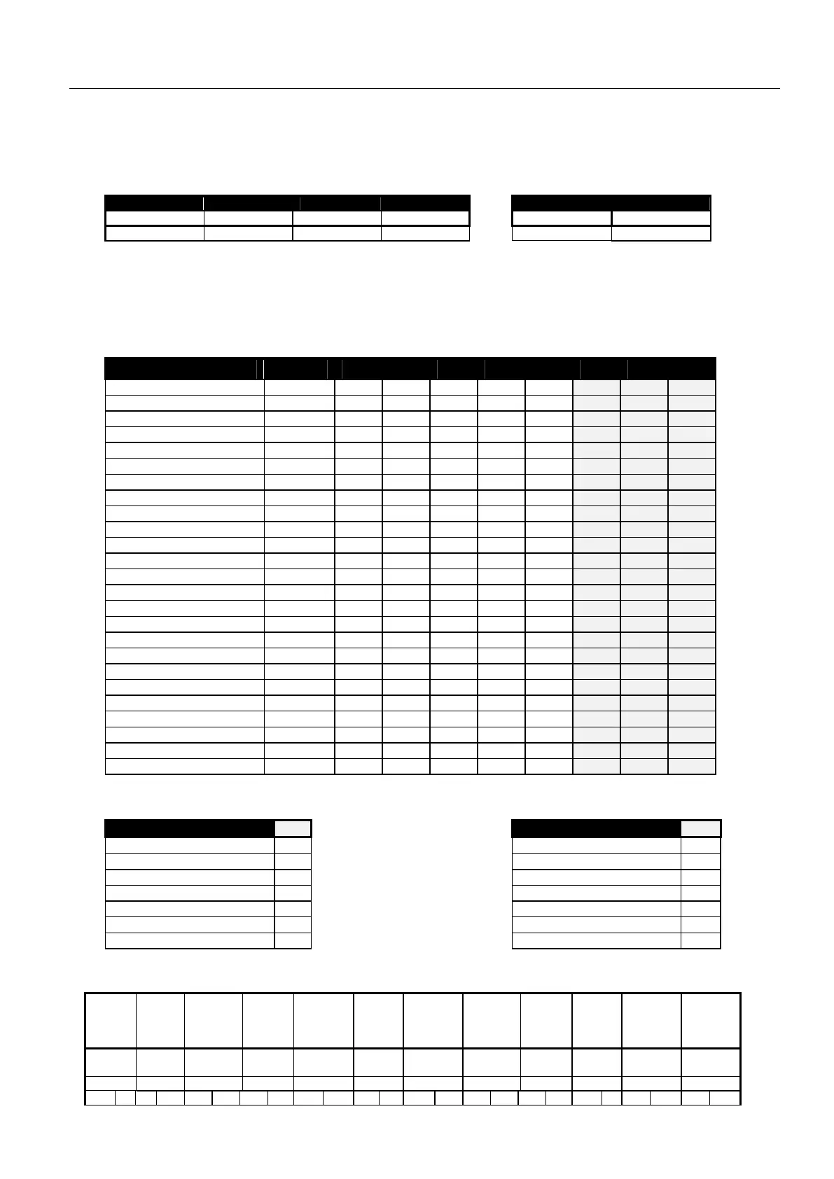
TELEPHONES SIGNAL TEST & AUTO ARMING TIME
Tel. 1 Tel. 2 Tel. 3 Tel. 4 Test Time Auto Arm Time
010 011 012 013 014 016
(00:01) 00:00
Tel. 1 is also the ‘Follow Me’. Maximum 16 digits + 4 pauses
Tel. 2 and 3 are communicator option.
Test signal to central station (014). Codes are defined at
Addresses: 072, 073, 237 & 255. Enter time in 24 hour
format
To insert * in the phone number, program system to dial in DTMF, Hold-down keys # and * (as panic); ‘A’ will
be displayed. For Pause during dialing, hold-down key ‘0’.
ZONE FEATURES
Feature Address
1 2 3 4 5 6 7 8
Fire zones 019
Zone In Use 020 1 2 3 4 5 6 7 8
Entry/Exit Delay 1 021 1
Entry/Exit Delay 2 022
Entry / Exit Follower 023 2
24-Hours Zone 024
Day Zone 025
Green Reset Zone 026 1 2 3 4 5 6 7 8
Swinger Shutdown 027
Chime 028 1 2
NON-EOL Resistor 029 1 2 3 4 5 6 7 8
Enable Zone Tamper 030
Delayed Power-Up 031
Fast Response 032
Group Bypass # 1 033
Group Bypass # 2
1
034
Manual Bypass 035 1 2 3 4 5 6 7 8
Siren Out 036 1 2 3 4 5 6 7 8
Alarm 1 (A1) Output 037 1 2 3 4 5 6 7 8
Reserved 038
SLO output (output 3)
2
039
Dial on Alarm 040 1 2 3 4 5 6 7 8
Sounder on Alarm 041 1 2 3 4 5 6 7 8
Normally Open (N.O.) 042
Panic Zone 045
1
Group Bypass # 2 – Available at PRO version 2.16 and latter.
2
SLO is a non-timed output. SLO = Selective output.
Address 043, 044 are applicable only with special Saturday (Shabbat) version.
Keypad Panic Alarm 050
Tamper Alarm 051
Siren on Panic 1 Tamper zone as 24H zone 1
Alarm 1 active on Panic 2 Alarm 1 active on Tamper 2
Reserved 3 Reserved 3
SLO On Panic (4) SLO on Tamper 4
Telephone Report (5) Tel. Line fail activates buzzer 5
Reserved 6 Tel. Line fail activates siren 6
Reserved 7 Dialer Report AC Power Fail 7
Values marked with ( ) are Factory Default Program. * Available with PRO type only
TIME-OUTS
AC fail
report
delay
Zone
Respons
e
time
Entry
Delay 1
Entry
Delay 2
**
Exit
Delay
**
Siren
Time
ON Siren
Time
OFF
Siren
Time
A1
Time
Reserv
ed
Chime
Time
Abort
Delay
Minutes m. Sec Sec's Sec's x
4
Sec's x 4 Minute
s
Sec's Sec's Sec's - Beeps Sec's
058 059 060 061 062 063 064 065 066 067 068 069
1 0 0 5 1 2 0 0 0 8 0 4 1 5 0 4 3 0 0 0 0 3 0 4
Note: Address 059 adjusts the response time of zones selected as ‘Fast Response,’ applicable with inertia sensors. ** Maximum value = 64.