14
*
7
4
1
0
8
5
2
#
9
6
3
Siren
Shunt
Display Status
Delay
Delete
Chime
Test Program Reset
Shunt
Teleph one
ARMED STATUS SHUNT FIRE
ZONE
DISPLAY
EASYLOADER AV-70 1
AV-GAD AV-GAD
EASYLOADER AV-70 1
FIRESHUNTSTATUSARMED
Test
Delete
Delay
Siren
1
4
7
*
DISPLAY
ZONE
Teleph one
Shunt
ResetProgram
Chime
StatusDisplay
Shunt
3
6
9
#
2
5
8
0 *
7
4
1
Siren
Delay
Delete
Test
ARMED STATUS SHUNT FIRE
EASYLOADER AV-70 1
AV-GAD
DISPLAY
ZONE
Teleph one
Shunt
ResetProgram
Chime
StatusDisplay
Shunt
3
6
9
#
2
5
8
0
AV-GAD
EASYLOADER AV-70 1
FIRESHUNTSTATUSARMED
Test
Delete
Delay
Siren
1
4
7
* 0
8
5
2
#
9
6
3
Shunt
Display Stat us
Chime
Program Reset
Shunt
Teleph one
ZONE
DISPLAY
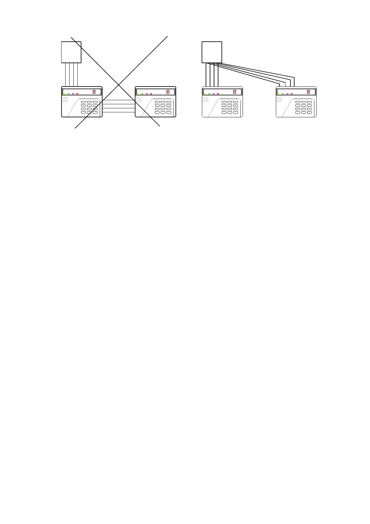
Panel
Panel
Wrong Wiring Correct Wiring
Figure 2A: Best Keypad Wiring
For trouble free system follow the recommended wiring of few keypads, as show in figure 2A, wire
each keypad to the panel directly, prevent wiring running from one keypad to next.
Keypad Tamper Switch
The AV-701TIP, AV-702TP, AV-706/707TP keypads (keypad with tamper switch) contains a
Tamper switch that is activated upon removing keypad’s front part. Connect the Tamper switch to
Tamper, Day or 24H zone. For connection, refer to keypad’s wiring diagram, figure 2.