Join the orange and grey revolution
AVA Wiring Options
AVA Wiring Options
As you will see from the previous page, our AVA electric actuators are capable of various
wiring conguraons based on what your applicaon requires. As detailed, our standard
for our Basic actuators is what we call B - B3S which is a SPDT with volt free posion
conrmaon. Our Smart actuators use E - B3J which is SPDT Relay posion conrmaon.
Remember that all of our Smart units don’t use mechanical cams and micro switches. A
digital encoder and relays are used. The following are some of the addional wiring dia-
grams that you might nd of interest, that are available for our Smart actuators including
3 and 4 posion wiring conguraons.
Check with your AVA reseller for lead me on non stock wiring conguraons.
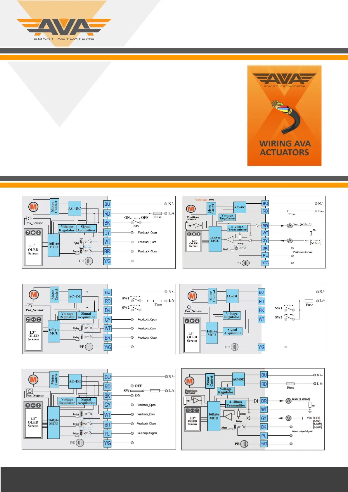
Wiring G: BD3J - SPST / Relay Posion Conrmaon Wiring P2: 4-20ma Failsafe with alarm output
Wiring J: B33J 2 x SPST / Relay Posion Conrm (3 posion) Wiring M: B44 SPST / No posion conrmaon (4 posion)
Wiring F: B3JA 2 x SPDT/Relay Posion Conrm + Alarm Output Wiring U5: 0-10V Control/ Feedback with Alarm Output
Revision: 002 Date: 05/06/20
 Loading...