EasyManua.ls Logo

Ava 200 Series - User Manual

Ava 200 Series
10 pages
Print Icon
To Next Page IconTo Next Page
Loading...
Join the orange and grey revolution
AVA 200 Series Overview
The AVA Basic is an entry level electric actuator designed where only minimal
features are required for on-o applicaons. The basic version is constructed tradionally
with internal cams striking micro-switches to stop the reversible motor in the required
posions. The lower torque models are available failsafe using capacitors.
Fully weatherproof to IP67 Dome style local visual indicator Hand operaon
End of travel conrmaon switches Female octagon drive output
Mulple ISO5211 mounngs An-condensaon heater
The AVA Smart
is a truly smart electric actuator designed to cover a wide range of funconal
applicaons, is fully electronic using digital magnec posioning and enrely run by
rmware. The smart version is recognisable by the introducon of a bright OLED screen
and external push buons that are used to set and adjust the AVA Smart actuator.
Available in ON OFF, Modulang, Failsafe, Failsafe Modulang, Timer, Wireless and
BUS. Standard features include:
OLED Screen User friendly local buon controls Brushless motors
An-condensaon heater Electronic torque limiter Many funconal opons
Standard Specicaons 200Nm
B200 Basic S200 Smart
Max Rated torque Nm output (in.lbs) Run 200Nm (1770) / 240Nm Break (2124) Run 200Nm (1770) / 240Nm Break (2124)
Voltage range 12VDC, 24VAC/DC, 95-265VAC 12VDC, 24VAC/DC, 95-265VAC
Mounng (ISO5211) x drive (female octagon) F07 & F10 x 22mm F07 & F10 x 22mm
Ingress Protecon IP67 IP67
Electrical connecon Conduit Wiring Box: 2 x M20 Conduit Wiring Box: 2 x M20
End of travel conrmaon (dry contact/volt-free) 2 x Mechanical micro-switches 2 x Electronic relays
Local visual posion indicator Dome style Dome style
LED Status light LED open/close/fault LED open/close/fault
Housing material ABS ABS
Weight ABS 6.0Kg 6.0Kg
Revision: 002 Date: 05/06/20
Dimensions:
Note that our smart actuator and basic actuators, regardless of funcon are all the same sizes per series.
Question and Answer IconNeed help?

Do you have a question about the Ava 200 Series and is the answer not in the manual?

Summary

AVA 200 Series Overview and Specifications

The AVA Basic Actuator

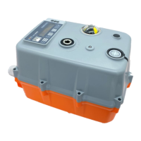
Entry-level electric actuator for on-off applications, featuring internal cams and micro-switches.

The AVA Smart Actuator

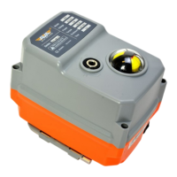
Smart electric actuator with digital magnetic positioning, OLED screen, and push buttons for configuration.

Standard Specifications 200 Nm

Comparison table for B200 Basic and S200 Smart actuators including torque, voltage, and ingress protection.

Series 200 Actuator Details

Power Consumption for Series 200

Details power consumption, peak current, and idle current for various voltage ranges across the 200 series.

Standard Features

Lists standard features like operating frequency, position confirmation, manual operation, and ingress protection.

Main Parts Identification

Diagram and list identifying the main components of the actuator.

AVA 200 Series Overview by Function

ON OFF Quarter Turn Actuators

Overview of basic and smart series for ON OFF quarter turn applications with voltage options.

Failsafe Quarter Turn Actuators

Overview of basic and smart series for Failsafe quarter turn applications with voltage options.

Modulating Quarter Turn Actuators

Overview of smart series for Modulating applications with signal inputs and voltage options.

Timer Quarter Turn Actuators

Overview of smart series for Timer applications with voltage options.

AVA 200 Series Wiring Diagrams

Basic Actuator Wiring

Wiring for basic ON OFF, Hi Speed, and Failsafe actuators using internal super capacitor.

Smart Actuator Wiring

Wiring for smart ON OFF, Hi Speed, and Failsafe actuators using digital encoder and relays.

Smart Modulating Wiring

Wiring for smart Modulating actuators requiring resistor fitting and feedback connection.

Smart Modbus RS485 Wiring

Wiring for smart actuators using Modbus RS485 for ON OFF or Failsafe applications.

Smart Timer Wiring

Wiring for smart Timer actuators, allowing schedule setting via onboard firmware.

Smart Wireless Wiring

Wiring for smart RF/Wireless actuators for local control via RF Fob.

Pre-Wired and Wiring Box Options

Details on pre-wired cables for series 10-50 and wiring box terminal strips for series 80-400.

Aviation Plug IP68 Connector

Information on plug-and-play IP68 weatherproof connectors for external applications.

AVA Basic Series - CAM Adjustment

Adjusting Valve Location Instructions

Step-by-step guide for adjusting full close and full open positions using internal cams and micro switches.

Wiring and Electrical Test

Instructions for wiring connections and performing electrical tests for valve position confirmation.

Smart Actuator OLED Screen Operation

OLED Screen User Guide - Basics

Guide to navigating the OLED screen, menu mode, local control, and button functions for customization.

Setting Positions and Failsafe

Instructions for electronically setting open/close positions, 3rd position, and failsafe options via the screen.

Advanced AVA Wiring Configurations

SPDT Relay Position Confirmation Wiring

Diagrams for BD3J, B33J, and B3JA wiring with relay position confirmation and alarm outputs.

4-20 mA Failsafe and 0-10 V Control Wiring

Diagrams for P2 (4-20mA Failsafe) and U5 (0-10V Control) with alarm outputs.

No Position Confirmation Wiring

Diagram for B44 wiring, featuring SPST and no position confirmation.

Installation, Operation & Maintenance

General Installation Guidelines

Covers cover removal, heater operation, orientation, IP rating, and wiring box usage.

Frequently Asked Questions & Fault Diagnosis

Addresses common issues like capacitor charge, alerts, no control, feedback errors, and screen issues.

Overview

The AVA 200 Series comprises a range of electric actuators designed for various applications, from basic on-off control to advanced modulating and smart functionalities. These actuators are engineered for reliability and ease of use, offering both traditional cam-based control and modern firmware-driven operation.

Function Description

The AVA 200 Series actuators are primarily designed for quarter-turn valve automation, providing precise control over valve positions. They convert electrical energy into mechanical rotational motion to open, close, or modulate valves. The series is broadly categorized into "Basic" and "Smart" versions, each offering distinct functionalities.

AVA Basic Actuators:

The AVA Basic is an entry-level electric actuator tailored for on-off applications where minimal features are required. It operates using a traditional mechanism where internal cams strike micro-switches to halt the reversible motor at the desired open or closed positions. Some lower torque models within the Basic series also offer a failsafe function, utilizing capacitors to return the valve to a predetermined safe position in the event of power loss. This version is ideal for straightforward control tasks that do not demand complex feedback or advanced diagnostic capabilities.

AVA Smart Actuators:

The AVA Smart series represents a more advanced and versatile range of electric actuators, designed to handle a wide array of functional applications. These actuators are fully electronic, employing digital magnetic positioning for precise control and are entirely run by firmware. This smart design allows for greater flexibility and advanced features compared to the Basic series. Smart actuators are easily identifiable by their bright OLED screen and external push buttons, which facilitate local setting and adjustment.

The Smart series offers multiple operational modes, including:

  • ON/OFF: For simple open and close operations.
  • Modulating: Allows for proportional control of the valve position, typically in response to a 4-20mA or 0-10V input signal. This enables precise flow regulation.
  • Failsafe: Incorporates a failsafe mechanism, often capacitor-based, to move the valve to a safe position upon power failure.
  • Failsafe Modulating: Combines proportional control with failsafe functionality.
  • Timer: Enables scheduled opening and closing operations based on an internal timer, allowing for automated control sequences.
  • Wireless: Facilitates control via wireless communication, suitable for installations where wired control is impractical.
  • BUS: Supports integration into larger control systems via communication protocols like Modbus RS485 or CANBUS, enabling remote monitoring and control.

Usage Features

Both Basic and Smart actuators are designed with user-friendly features to ensure straightforward installation, operation, and adjustment.

General Usage Features (Common to both Basic and Smart):

  • Weatherproof Design: Fully weatherproof to IP67 standards, making them suitable for various environmental conditions.
  • Local Visual Indicator: Both series feature a dome-style local visual indicator, providing a clear visual representation of the valve's current position (open, closed, or in between).
  • Manual Operation: A manual override mechanism is included, allowing for manual positioning of the valve using a hexagonal wrench (supplied in a clip) when power is not available. For the Smart series, a declutch button on the cover must be engaged first to enable manual override, and then pressed again to disengage and allow electric control.
  • End of Travel Confirmation: Both series provide end-of-travel confirmation. Basic actuators use mechanical micro-switches, while Smart actuators use electronic relays to signal the fully open or closed positions.
  • Drive Output: Both feature a female octagon drive output, compatible with standard valve stem configurations.
  • Mounting: Designed with multiple ISO5211 mountings, ensuring compatibility with a wide range of valves.
  • Anti-condensation Heater: An anti-condensation heater is a standard feature, helping to prevent internal moisture buildup and prolonging the actuator's lifespan.
  • Electrical Connection: Both series utilize a conduit wiring box with M20 glands for electrical connections.

Specific Usage Features for AVA Smart Actuators:

  • OLED Screen: A bright OLED screen displays actuator status, set position from PLC/Controller, actual position, and alerts (e.g., over torque).
  • User-friendly Local Button Controls: External push buttons allow users to navigate menus, customize settings (working angle, speed, accuracy), and operate the actuator locally in Manual or Local Control modes.
  • Brushless Motors: Smart actuators incorporate brushless motors, which typically offer longer lifespan, higher efficiency, and quieter operation compared to brushed motors.
  • Electronic Torque Limiter: A standard feature that protects the valve and actuator from damage due to excessive torque.
  • Firmware-driven Position Adjustment: Unlike Basic actuators that rely on physical cams, Smart actuators adjust valve position via firmware settings, offering greater precision and flexibility. This includes setting open, close, and even a third position (B33) for 3-way valves or 3-point control.
  • Capacitor Charge Display: For failsafe Smart actuators, the OLED screen displays the capacitor charge percentage, and users can set the minimum required charge percentage and the failsafe position (open or closed).
  • Advanced Wiring Options: Smart actuators support a variety of wiring configurations for Modbus, Wireless, and Timer functions, allowing for integration into complex control systems.

Maintenance Features

The AVA 200 Series actuators are designed for minimal maintenance, with several features contributing to their long-term reliability.

General Maintenance Features (Common to both Basic and Smart):

  • Maintenance-Free Design: All series of AVA actuators are designed to be maintenance-free. Regular operation is recommended to ensure optimal performance.
  • No Cover Removal for Basic Maintenance: Users are advised not to remove the cover unless instructed by an AVA reseller or technical support, as doing so may invalidate the warranty.
  • Heater Operation: The anti-condensation heater is prewired and operates automatically when the actuator is powered, preventing moisture buildup without user intervention.
  • Keep Powered Recommendation: It is recommended to keep the actuators powered at all times to ensure the heater and feedback mechanisms operate continuously.
  • Robust Housing: The housing material is ABS plastic, known for its durability and resistance to environmental factors.

Specific Maintenance Considerations:

  • Basic Actuator Cam Adjustment: For Basic actuators, position adjustment involves physically adjusting internal cams and micro-switches. This process requires careful attention to torque settings to avoid damaging the locating driving gear or screw threads.
  • Smart Actuator Firmware Updates: As Smart actuators are firmware-driven, potential updates or reconfigurations can be managed through the OLED screen and button interface, offering a modern approach to maintenance and customization.
  • Diagnostic Alerts: Smart actuators can display "ALERT" messages on the OLED screen for issues such as "Excessive Valve Torque" or "Motor Failure," aiding in quick diagnosis and troubleshooting.
  • Wiring Box Access: For larger actuators (Series 80-400Nm), a wiring box at the rear can be removed to expose the terminal strip for wiring, simplifying installation and potential troubleshooting of electrical connections.
  • Warranty: Basic series actuators come with a standard 1-year, 20,000 operations warranty, while Smart series actuators offer an upgraded 2-year, 60,000 operations warranty, reflecting their enhanced design and durability.

In summary, the AVA 200 Series provides a comprehensive range of electric actuators, from robust basic models to advanced smart versions, all designed with a focus on functionality, ease of use, and minimal maintenance.

Ava 200 Series Specifications

General IconGeneral
Ethernet Ports2 x 10/100/1000 Mbps
USB Ports2 x USB 2.0
CategoryController
Operating SystemLinux-based
Serial Ports2 x RS-232/485
Power Supply24 VDC
Dimensions150 mm x 100 mm x 50 mm

Related product manuals