Revision: 002
Join the orange and grey revolution
AVA Basic Series - CAMS
Adjusting valve location
instructions
1. ADJUSTING FULL CLOSE POSITION
Rotate the valve to full close posion with handle.
• Since the valve has gone through “factory default seng”, this step can be omied if it the adjustment is slight.
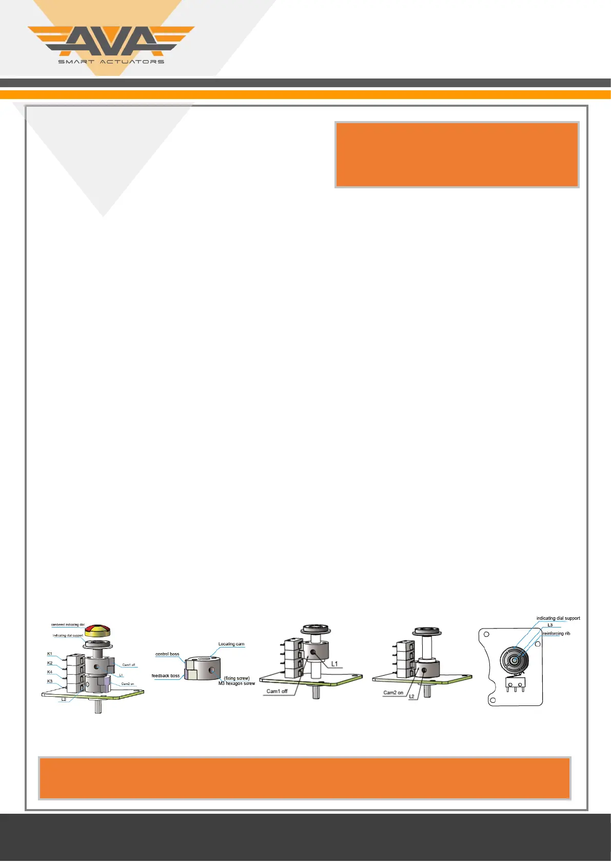
• Detach cambered indicang dial, loosen xing screw L3 of indicang dial support, turn reinforcing rib as shown in diagram 5,
perpendicular to the ow direcon of valve, then screw up L3 and buckle up cambered indicang dial.
• Loosen xing screw L1 of cam 1, drive cam 1 to rotate clockwise and trigger micro switches K2, K1 to move in turn and make
sound. When K1 moves and makes sound, stop adjustment. Then screw up xing screw L1.
• Noce 1: The default is that rotang in clockwise direcon means closing ,and rotang in anclockwise direcon means
opening.
• Noce 2: B3P does not have K2,K4 micro switch.
Cauon: When screwing up L3, the torque≤0.5 NM, otherwise it will damage locang driving gear.
In the process of adjustment, do not over ghten screws, otherwise it will damage screw threads or other parts.
2. ADJUSTING FULL OPEN POSITION
• Rotate the valve to full open posion with handle.
• Loosen xing screw L2 of cam2, drive cam 2 to rotate anclockwise and trigger micro switches K4, K3 to move in turn and
make sound. When K3 moves and makes sound, stop adjustment. Then screw up xing screw L2.
3. WIRING
• Aer modifying, connect the circuit according to the wiring label on the box cover. Aer conrmaon, you can do power test.
4. ELECTRICAL TEST
• Mainly check the consistence of on and o between the actuator and the valve body. At the same me, please check whether
the valve is full close or not. Special tesng device is recommended
Diagram 1 Diagram 2 Diagram 3 Diagram 4 Diagram 5
Note you should only remove the cover on instrucon
from your AVA reseller or AVA technical support agent
as it may invalidate warranty.
NOTE - Smart actuators do not have internal cams and micro switches, therefore posion adjustment is via rmware. See
actuator Firmware User Guide for detailed screen by screen guide including how to change working angle and feedback.
 Loading...