EAX-Q35
2
Contents
Safety Information ..........................................................................................................4
Technical Support ............................................................................................................5
Conventions Used in This Guide ....................................................................................5
Packing List .......................................................................................................................6
Revision History ...............................................................................................................7
Specifications Summary..................................................................................................8
Block Diagram.................................................................................................................11
Production Introduction ...............................................................................................13
1.1 Before you Proceed ................................................................................................13
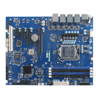
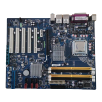
1.2 Motherboard Overview............................................................................................14
1.2.1 Placement Direction ....................................................................................................................... 14
1.2.2 Screw Holes ................................................................................................................................... 14
1.3 Motherboard Layout ................................................................................................15
1.3.1 Layout Content List ........................................................................................................................ 16
1.4 Central Processing Unit (CPU)................................................................................18
1.4.1 Installing the CPU........................................................................................................................... 19
1.4.2 Installing the CPU Heatsink and Fan ............................................................................................. 21
1.4.3 Uninstalling the CPU Heatsink and Fan......................................................................................... 23
1.5 System Memory ......................................................................................................25
1.5.1 DIMM Sockets Location ................................................................................................................. 25
1.5.2 Memory Configurations .................................................................................................................. 26
1.5.3 Installing a DDR2 DIMM................................................................................................................. 27
1.5.4 Removing a DDR2 DIMM............................................................................................................... 27
1.6 Expansion Slots ......................................................................................................28
1.6.1 Installing an Expansion Card ......................................................................................................... 28
1.6.2 Configuring an Expansion Card ..................................................................................................... 28
1.6.3 Standard Interrupt Assignments..................................................................................................... 29
1.6.4 PCI Slot .......................................................................................................................................... 30
1.6.5 PCI Express X16 Slot..................................................................................................................... 30
1.7 Jumpers ..................................................................................................................31
1.7.1 Clear CMOS (CLRTC).................................................................................................................... 31
1.7.2 Chassis Intrusion Connector (CHSSIS) ......................................................................................... 32
1.7.3 COM1, 2, 3, 4 RI/+5V/+12V Select (JCOMPWR1, 2, 3, 4) ............................................................ 32
1.7.4 COM4 RS-242/422/485 Select (JCOMPWR5, 6, 7) ...................................................................... 33