This document serves as a service manual for Avantco Refrigerated Pizza Prep Tables, specifically models #178APPT49HC, #178APPT71HC, and #178APPT91HC. These units are designed for commercial use, providing refrigerated storage and a preparation surface for pizza ingredients. The manual is intended for certified service technicians and emphasizes that it should not be used by untrained individuals. It covers troubleshooting, part testing, and part replacement procedures, along with detailed diagrams and settings for the temperature controller.
Function Description
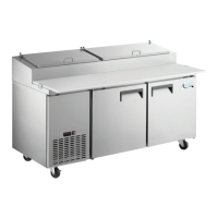
The Avantco Refrigerated Pizza Prep Tables are commercial refrigeration units that combine refrigerated storage with a convenient preparation surface. They are designed to keep pizza ingredients, such as cheeses, meats, and vegetables, at safe and consistent temperatures while providing a durable worktop for assembling pizzas. The units feature multiple doors for accessing refrigerated compartments and a top section for holding ingredient pans. An integrated temperature controller manages the internal temperature, and various components like compressors, fans, and heaters work in conjunction to maintain optimal operating conditions.
Important Technical Specifications
The manual provides specific model numbers and their corresponding sizes:
- #178APPT49HC: 49" 1 Door Refrigerated Pizza Prep Table
- #178APPT71HC: 72" 2 Door Refrigerated Pizza Prep Table
- #178APPT91HC: 91" 3 Door Refrigerated Pizza Prep Table
Compressor Specifications (Max Load Amps and Locked Rotor Amps (LRA) at 70°F):
- 178APPT49HC: Max Load Amps: 4 Amps, LRA: 13.2 Amps
- 178APPT71HC: Max Load Amps: 5 Amps, LRA: 16.4 Amps
- 178APPT91HC: Max Load Amps: 7 Amps, LRA: 28.6 Amps
Compressor Winding Resistance (at 70°F):
- Run to Start: 10 Ω +/- 10%
- Run to Common: 3 Ω +/- 10%
- Start to Common: 7 Ω +/- 10%
Capacitor Specifications:
- Micro-farads: 10 +/- 5%
- Discharge resistor: 20,000 ohm, 2 watt carbon resistor
Door Seal Heater:
- Resistance: 220 Ω at 70°F +/- 10%
- Amperage: 0.5 amps (on black wire after red connector)
Capillary Tube:
- 178APPT49HC: 0.036" ID x 80" Lg
- 178APPT71HC: 0.036" ID x 80" Lg
- 178APPT91HC: 0.046" ID x 58" Lg
Temperature Controller Settings (Carel Controller):
- P5 (Password setting): Range 0-200, Default 22 (recommended not to change)
- /5 (Temperature Unit F/C): 0 = °C, 1 = °F, Default 1 (°F)
- /c1 (Cabinet Offset): -50.0° to 50.0°, Default 0°
- /c2 (Evap Offset): Not used on Refrigerators, Default 0
- rd (Differential): 0°F to 19°F, Default 5°F
- r1 (Low Limit): -50°F to r2, Default 33°F
- r2 (Hi Limit): r1 to 200°, Default 43°F
- c0 (Compressor Delay): 0 to 100 minutes, Default 2 minutes
- dl (Defrost Interval Time): 0 to 199 hours, Default 6 hours
- dt1 (Defrost Termination Temp): -50°F to 130°F, Not used on Refrigerators
- dP1 (Max Defrost Duration): 1 to 199 minutes, Default 20 minutes
Usage Features
The primary usage feature of these units is their ability to maintain precise temperatures for food safety while offering a practical workspace. The temperature controller allows for customization of settings such as temperature unit, cabinet offset, differential, and defrost intervals. Users can adjust these parameters to suit their specific operational needs, although some settings like the password and defrost termination temperature are either fixed or not applicable for these refrigerator models. The inclusion of multiple doors and lids facilitates organized storage and easy access to ingredients.
Maintenance Features
The manual provides comprehensive instructions for troubleshooting, part testing, and part replacement, making it a valuable resource for certified service technicians.
Troubleshooting:
The troubleshooting section addresses common issues such as the unit not turning on, not reaching the set temperature, not holding the set temperature, and water coming from the drain/pan. It provides a checklist of possible solutions, including:
- Checking power supply and connections.
- Inspecting door gaskets and ensuring proper closure.
- Verifying that all pans are installed.
- Ensuring ambient air temperature is below 85°F.
- Cleaning condenser and evaporator coils.
- Checking controller settings and default parameters.
- Verifying the operation of evaporator and condenser fans.
- Checking compressor operation and cabinet temperature sensor.
- Inspecting the drain pan hose for clogs.
Part Testing:
Detailed procedures are outlined for testing critical components:
- Compressor & Capacitor: Involves checking amperage, resistance of windings (Run to Start, Run to Common, Start to Common), and for grounding issues. It also covers visual inspection and micro-farad testing of the capacitor, with a caution to discharge it using a 20,000 ohm, 2 watt carbon resistor.
- Controller: Instructions for checking 120 volts between specific terminals (white (N) and black (L), white (N) and red (Compressor)) and inspecting for discoloration or deformation of electrical connections.
- Power Switch: Steps to check 120 volts at various points of the switch in both 'OFF' and 'ON' positions, and to inspect electrical connections.
- Evaporator Fan Motor: Checking 120 volts between white (N) and black (L) wires and inspecting connections.
- Condenser Fan Motor: Checking 120 volts at the fan plug and 0.5 amps at the black wire when the compressor is running, along with inspecting connections.
- Door Seal Heater: Disconnecting power, checking resistance (220 Ω at 70°F +/- 10%), checking 120 volts between white and black wires, and checking 0.5 amps on the black wire after the red connector.
Part Replacement:
The manual offers step-by-step instructions for replacing various components, emphasizing the importance of turning off and disconnecting power before servicing, and adhering to all EPA, federal, and local guidelines when working with refrigerants, especially flammable ones. All connections where refrigerant travels must be checked for leaks after brazing.
- Controller: Involves removing the control panel, top cover, pushing in yellow brackets, sliding the controller, pushing it through the cutout, and disconnecting wires.
- Condensing Tray Components (Compressor, Capacitor, Filter Drier, Condenser Fan Cover, Blade, Motor, Coil): Detailed steps include removing the control panel, screws for the condensing tray, pulling out the tray, cutting refrigerant lines (with EPA warnings), removing wiring covers, disconnecting wires, unbolting the compressor, discharging and unbolting the capacitor, cutting process and liquid lines for the filter drier, removing fan covers, unscrewing fan blades, and cutting copper lines for the condenser coil.
- Evaporator Compartment Parts (Evaporator Fan Blade, Motor, Coil): Instructions include opening the door, removing shelves, unscrewing the evaporator panel, removing fan blade screws, removing fan motor brackets and screws, unscrewing wire clamps, unplugging the motor, removing screws for the top cover, and cutting silicone seals. The process for replacing the evaporator coil involves lifting the top off the base, removing screws from the coil cover plate, cutting copper tubes (with warnings about capillary tube obstruction), and removing screws holding the coil to the cabinet walls.
The manual also includes detailed wire diagrams for each model (178APPT49HC, 178APPT71HC, 178APPT91HC) and extensive parts diagrams with corresponding item numbers, descriptions, and part numbers, facilitating easy identification and ordering of replacement parts.