EasyManua.ls Logo

Avaya 4850GTS Series - User Manual

Avaya 4850GTS Series
8 pages
Print Icon
To Next Page IconTo Next Page
Loading...
2
Unpack the equipment and verify
package content
Confirm that you have the following tools and cables:
• Phillips #2 screwdriver
Console cable to match the console connector on the
switch (DB-9 or RJ-45)
ESD cable
Virtual Services Platform
4000 4850GTS Series
Quick Install Guide
Avaya
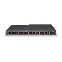
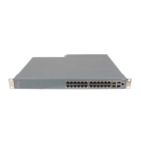
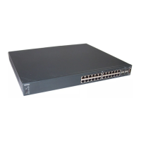
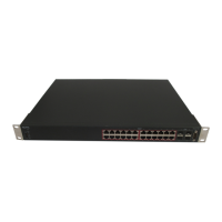
1. Avaya Virtual Services Platform (VSP) 4000 Series switch with
one power supply installed.
2. Rack-mounting hardware that includes:
a. Rack-mount brackets
b. Screws to attach brackets to the switch
c. Screws to attach the switch to the equipment rack
3. Rubber footpads
4. AC power cord with an IEC 60320 C16 connector.
(Note: A power cord is not included for the A variant of
the switch.)
5. Documentation that includes the following:
a. Locating the latest software and product
Release Notes (NN46251-106)
b. The Regulatory guide (NN46251-105)
c. The Quick Install guide (this document)
d. The China RoHS paper.
1
Before you start
This document provides information and instructions to
install and commission a factory-supplied Avaya Virtual
Services Platform 4000 switch. You can download all docu-
ments referenced in this guide at www.avaya.com/support.
Optionally order a redundant PSU to provide redundancy, load
sharing, and add Power over Ethernet Plus (PoE+) power budget
on PWR+ models.
VSP 4000 AC power specifications
(VSP 4850GTS and VSP 4850GTS-PWR+):
Note: Both the 300W and 1000W AC power supplies use the IEC
60320 C16 AC power cord connector.
The VSP 4000 Series switch supports two field-replaceable power
supplies. One power supply is installed. You can optionally install a
redundant power supply. The VSP 4000 switch comes in AC and
DC power variants.
Use this procedure to install a redundant power supply.
Note: The switch ships with a filler panel in the second power
supply position. This filler panel must stay in place if you do not
intend to install a second power supply.
If you mount the VSP 4000 switch on a table or shelf, attach the
rubber feet to the device as indicated. The surface must support
the combined weight of the switch and attached cables (from 15
to 20 pounds [7 to 9 kilograms]).
Set the device on a flat surface near an AC power source,
making sure there is at least 2 inches (5.1 cm) of space on all
sides for proper air flow, and at least 5 inches (12.7 cm) at the
back for power cord clearance.
b. Rack mounting
3.
Slide the switch into the rack as illustrated. Insert and tighten the
rack-mount screws.
Note: Observe ESD precautions when unpacking.
3
Verify power supply unit (PSU)
specifications
VSP 4000
model
Primary
PSU
Redundant PSU
(to be ordered if required)
VSP 4850 GTS
300w AC
power supply
(replacement
order code:
AL1905?08-E5)
300w AC power supply
(order code: AL1905?08-E5)
Note: The seventh character (?) of the
switch order number must be replaced
with the proper letter to indicate desired
product
nationalization.
“A”: No power cord included.
“B”: Includes European “Schuko”
power cord common in Austria,
Belgium, Finland, France, Germany,
The Netherlands, Norway,
and Sweden.
“C”: Includes power cord commonly
used in the United Kingdom
and Ireland.
“D”: Includes power cord commonly
used in Japan.
“E”: Includes North American
power cord.
“F”: Includes Australian power cord.
VSP 4850
GTS-PWR+
1000w AC PoE+
power supply
(replacement
order code:
AL1905?21-E6)
1000w AC power supply
(order code: AL1905?21-E6)
PoE+ specifications:
Maximum PoE+ Wattage:
855W with one power supply
1855W with two power supplies
Average PoE+ Wattage on 50 port models:
15.4W (802.3af)
17.8W (802.3.at) 1 power supply
32.4W (802.3at) 2 power supplies
The VSP 4850GTS-PWR+ can support 802.3af 15.4W on
each port with one power supply installed.
PoE+ power reduces to an average of 17.8W on each port
with one power supply. It can support 802.3at 32.4W on
each port with two power supplies installed.
VSP 4000 DC power specification (VSP 4850GTS):
VSP 4000 model Primary PSU Redundant PSU
VSP 4850
GTS DC
300w DC power supply
(replacement order code:
AL1905?05-E5)
300w DC power supply
(order code:
AL1905?05-E5)
DC Power supply specifications:
Input voltage: 48 V DC
Input current: 10 A
Output voltage: 12 V DC
Output current 25 A
4
(Optional) Install redundant
power supply unit
1.
If a blanking plate covers the required power supply slot,
remove the blanking plate before attempting to insert the
power supply.
2. Insert the power supply into a rear power supply slot as
shown below:
3. Verify that each power supply is fully seated in the slot.
Secure the power supply with the two thumb screws.
Note: The switch chassis can prevent an incorrect installation
of a power supply. If you insert a power supply upside down, it
will not fully insert and the thumb screws will not engage.
4. After you install a power supply, proceed with connecting
AC power.
5
Mount the VSP 4000 switch
a. Table or Shelf mounting
Prepare the rack:
1. Provide the equivalent of one RU of vertical space for each
switch in an EIA or IEC-standard 19-inch (48.2-centimeter)
equipment rack.
Ensure that the equipment rack is stable and securely attached
to a permanent structure.
2. Ground the rack to the same grounding electrode used by the
power service in the area. The ground path must be permanent
and must not exceed 1 ohm of resistance from the rack to the
grounding electrode. AVAYA recommends using a filter or
surge suppressor.
Mount the switch:
1. Remove the screws that hold the USB cover for rack mounting,
but do not remove the USB cover.
Caution: Do not remove the USB
device from the slot. This can
seriously affect switch operation and
may even cause the switch to not
boot up. Ensure that the USB device
is inserted at all times, with the USB
cover on.
2. Attach a bracket to each side of the switch using the #2 Phillips
screw-driver as illustrated. The bracket goes over the USB cover.
For more details on installing the VSP 4000 Series, see
Installing the Avaya Virtual Services Platform 4000
VSP4850GTS Series (NN46251-300).
1
2
3
4
5
6
7
8
11
12
9
10
13
14
15
16
17
18
19
20
23
24
21
22
25
26
27
28
29
30
31
32
35
36
33
34
37
38
39
40
41
42
43
44
47
48
45
46
4850GTS-PWR+
1
2
3
4
5
6
7
8
11
12
9
10
13
14
15
16
17
18
19
20
23
24
21
22
25
26
27
28
29
30
31
32
35
36
33
34
37
38
39
40
41
42
43
44
47
48
45
46
4850GTS-PWR+
PWR
RPS
Up
Do
wn
Bas
e
US
B
Spee
d
Spee
d
V
S
P
PW
R
Status
R
PS
Up
Down
Base
USB
S
pee
d
S
pee
d
V
S
P
1
2
3
4
5
6
7
8
11
12
9
10
13
14
15
16
17
18
19
20
23
24
21
22
25
26
27
28
29
30
31
32
35
36
33
34
37
38
39
40
41
42
43
44
47
48
45
46
4850
GTS-PWR+
1
2
3
4
5
6
7
8
11
12
9
10
13
14
15
16
17
18
19
20
23
24
21
22
25
26
27
28
29
30
31
32
35
36
33
34
37
38
39
40
41
42
43
44
47
48
45
46
4850
GTS-PWR+
Question and Answer IconNeed help?

Do you have a question about the Avaya 4850GTS Series and is the answer not in the manual?

Summary

Unpack Equipment and Verify Package Content

VSP 4000 Series Switch Unit

The main switch unit with one power supply installed.

Verify Power Supply Unit (PSU) Specifications

Mount the VSP 4000 Switch

Rack Mounting

Procedure for installing the switch into an equipment rack.

Mount the Switch in Rack

Procedure for attaching brackets and securing the switch within the equipment rack.

Power Up the Switch

Connect AC Power

Connecting the AC power cord to the switch and outlet, noting dual cord requirement for redundant PSU.

Verify Power Indicators

Checking front-panel LEDs, specifically the PWR LED, to confirm correct power connection.

Install SFP and SFP+ Transceivers

Insert Transceiver into Slot

Procedure for inserting the transceiver into the SFP/SFP+ slot until it clicks and locks.

Commissioning the VSP 4000

Connect Console Cable to Switch

Connecting the console cable to the switch for initial configuration.

Shutting Down the VSP 4000

Overview

The Avaya Virtual Services Platform (VSP) 4000 4850GTS Series is a network switch designed for enterprise environments, offering robust connectivity and advanced features for managing network traffic. This Quick Install Guide provides essential information for the initial setup and commissioning of the device.

Function Description

The VSP 4000 4850GTS Series switch serves as a core component in a network infrastructure, facilitating high-speed data transfer and network management. It is designed to handle various network demands, from basic connectivity to more complex Power over Ethernet Plus (PoE+) applications. The switch supports both AC and DC power variants, offering flexibility in deployment scenarios. Its primary function is to connect network devices, manage data flow, and provide a reliable and scalable network backbone. The optional redundant power supply unit (PSU) enhances reliability by providing fault tolerance and load sharing, which is crucial for maintaining continuous network operation. For PoE+ models, the redundant PSU also increases the available power budget, allowing for more powered devices to be connected.

Usage Features

The VSP 4000 4850GTS Series offers several usage features that simplify deployment and operation:

  • Flexible Mounting Options: The switch can be deployed in multiple ways to suit different physical environments. For table or shelf mounting, rubber footpads are provided to ensure stability. Adequate clearance (at least 2 inches on all sides and 5 inches at the back for power cord clearance) is recommended for proper airflow. For rack mounting, the switch occupies one Rack Unit (RU) of vertical space in an EIA or IEC-standard 19-inch equipment rack. Rack-mounting hardware, including brackets and screws, is included for secure installation.
  • Power Supply Flexibility: The switch ships with one power supply installed, but it supports two field-replaceable power supplies. Users can optionally install a redundant power supply to enhance network uptime and distribute power load. The installation process for the redundant PSU is straightforward, involving the removal of a blanking plate and insertion of the new PSU into a rear slot. Proper seating and securing with thumb screws are emphasized to prevent incorrect installation.
  • Easy Power-Up Procedure: Connecting the AC power cord to the back of the switch and then to an AC power outlet initiates the power-up sequence. The front-panel PWR LED indicates successful power-on. In case of a redundant PSU installation, two power cords are required.
  • SFP and SFP+ Transceiver Support: The switch supports Small Form-Factor Pluggable (SFP) and SFP+ transceivers, allowing for flexible network cabling options and connectivity to various network devices. The installation of transceivers is a simple process of inserting them into the designated slots until they click and lock into position. This modularity enables users to adapt the switch to specific network configurations and future expansion needs.
  • Console Port for Initial Configuration: The VSP 4000 features an RJ-45 console port, outlined with a blue border, for initial configuration and management. This port allows connection to a management terminal (PC or other device) using a console cable (RJ-45 to DB-9 or RJ-45 to RJ-45) and appropriate adaptors. The maximum length for the console port cable is 25 feet (8.3 meters). Terminal emulation settings (Baud Rate, Data Bits, Stop Bits, Parity, Flow Control) are provided to ensure proper communication.
  • VLAN Configuration: The guide outlines steps for configuring an in-band VLAN and a management IP interface for the VLAN. This allows for network segmentation and remote management of the switch, enhancing security and operational efficiency.
  • Safe Shutdown Procedure: A critical usage feature is the recommended shutdown procedure. Before unplugging the AC power cord, users are instructed to enter specific commands (enable followed by sys shutdown) to ensure all pending data is flushed and data integrity is maintained. Waiting for the "System Halted, OK to turn off power" message confirms a safe shutdown.

Maintenance Features

While the guide primarily focuses on installation, several aspects touch upon maintenance:

  • Field-Replaceable Power Supplies: The ability to install and replace power supplies in the field is a significant maintenance feature. This modular design allows for quick replacement of faulty PSUs without requiring the entire switch to be taken offline, minimizing downtime.
  • ESD Precautions: The guide explicitly states to "Observe ESD precautions when unpacking." This is a crucial maintenance practice to prevent electrostatic discharge damage to sensitive electronic components during handling and installation, thereby extending the lifespan of the device.
  • Documentation for Ongoing Support: The guide references various documents available on www.avaya.com/support, including "Locating the latest software and product Release Notes," "The Regulatory guide," "Documentation Reference," "Installation," "Quick Start Configuration," "Release Notes," and "Administration." These resources are essential for ongoing maintenance, troubleshooting, and understanding the full capabilities of the VSP 4000 Series switch. They provide detailed information on software updates, regulatory compliance, advanced installation procedures, and administrative tasks, all of which contribute to the long-term health and performance of the device.
  • USB Device Caution: A specific caution regarding the USB device in the slot highlights a maintenance consideration. Users are warned not to remove the USB device, as it can seriously affect switch operation and boot-up. This emphasizes the importance of understanding specific hardware requirements for proper device function and avoiding actions that could lead to system instability.
  • Grounding Requirements: For rack mounting, the guide specifies the need to ground the rack to the same grounding electrode used by the power service, ensuring a permanent ground path with resistance not exceeding 1 ohm. This is a critical safety and maintenance measure to protect the equipment from electrical surges and ensure stable operation. Avaya recommends using a filter or surge suppressor for added protection.

Avaya 4850GTS Series Specifications

General IconGeneral
Jumbo Frame SupportYes
Power SupplyInternal
Product TypeSwitch
Uplink Ports4
Layer3
Rack Units1U
MAC Address Table Size32K
FeaturesVLAN, QoS, IPv6
Ports48

Related product manuals