You can download all documents referenced in this Quick Installation Guide at
www.avaya.com. You do not require a support contract to download documents.
When downloading documentation, select the specific software version. Depending on
your hardware model, your switch can appear different than the figures shown in this guide.
Confirm that you have the following tools and package contents:
Tools required:
• Phillips #2 screwdriver
• Console cable to match the console connector on the switch (RJ-45)
• Console cable or Ethernet cable (if using the default IP address to access the
device for configuration)
Package contents:
REPLACEMENT/OPTIONAL POWER SUPPLY UNITS
Primary PSU Optional Secondary PSU
ERS 4950GTS-PWR+,
ERS 4926GTS-PWR+
ERS 4950GTS,
ERS 4926GTS
250W AC power supply
(replacement order code:
AL1905?09-E6)
1025W AC POE+ power supply
(replacement order code:
AL1905?19-E6)
250W AC Power Supply
(order code: AL1905?09-E6)
1025W AC power supply
(order code: AL1905?19-E6)
Model
CABLES FOR INSTALLING THE SWITCH INTO A NETWORK
Name Short DescriptionPEC Code
AL2011022-E6 Avaya RJ-45/DB-9
CONSOLE CABLE
1.5m cable with DB-9 Female for
terminal/PC on one end and RJ-45
for device console port connectivity
on the other.
AL2011021-E6 AVAYA BLUE DB-9
MALE TO RJ-45
CONSOLE CONNECTOR
Converts DB-9 of AL2011013-E6
console cable to RJ-45, a Category 5
RJ-45 straight cable can then
connect to RJ-45 console port.
AL2011020-E6 AVAYA RED DB-9 FEMALE TO
RJ-45 ADAPTOR
Converts DB-9 MALE to RJ-45 serial
port. The adaptor can be used for PC
or device with DB-9 MALE console
port. Also, can be used with Category 5
RJ-45 straight cable to provide
console connection.
STACKING CABLES FOR STACKING
Description
700511668
700511669
700511670
700511671
0.5 m stacking cable
1.5 m stacking cable
3.0 m stacking cable
5.0 m stacking cable
Material code
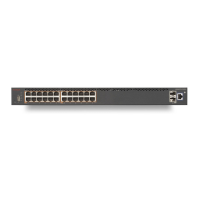
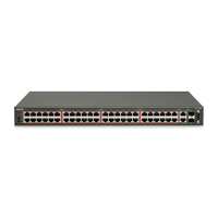
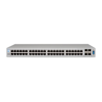
Ethernet Routing
Switch 4900 Series
1. Avaya Ethernet Routing Switch 4900 Series.
2. Rack-mounting hardware that includes:
• Rack-mount brackets (2)
• Screws to attach brackets to the switch (8)
Note: Screws to attach the rack mount kit to rack are not provided.
3. AC power cord.
(Note: A power cord is not included for the A variant of the switch)
4. Standard .5 m stacking cable.
5. Documentation includes the Base software license kit, Quick Install poster,
and Regulatory documents.
6. Field replaceable power supply.
Note: Two field replaceable power supplies are supported for models ERS 4950GTS,
ERS 4926GTS, ERS 4950GTS-PWR+, and ERS 4926GTS-PWR+. One power supply is
already installed.
Note: Ensure to order Direct Attach cables and SFP or SFP+ Transceivers
if required.
Other optional requirements:
1. Provide the equivalent of one rack of vertical space for each switch in an EIA or
IEC-standard 19-inch (48.2-centimeter) equipment rack.
2. Ensure that the equipment rack is stable and securely attached to a
permanent structure.
3. Ground the rack to the same grounding electrode used by the power service in the
area. The ground path must be permanent and must not exceed 1 Ohm of
resistance from the rack to the grounding electrode. AVAYA recommends using a
filter or surge suppressor.
1.
Attach the brackets to each side of the device using the screws provided.
2. Slide the switch into the rack. Insert and tighten the rack-mount screws.
Avaya
1
Before you start
Quick Installation for Avaya Ethernet Routing Switch 4900 Series
2
3
Front-mount the switch in a rack
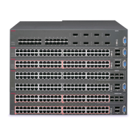
The Avaya ERS 4900 Series provides fail-safe stackability. You can connect up to eight 4900
Series devices in a stack to provide uninterrupted connectivity for up to 400 ports. The stack is
managed as single unit, using the IP address of the base unit.
ERS4900 series rear panel
The switch back panel provides a Base Unit Select switch, Cascade Down connector, and
Cascade Up connector for stacking purposes as shown below:
4
Stacking
Base Unit Select switch – used to designate the base unit in a stack. When set DOWN, this unit
acts as the Base Unit for the stack. Only one switch in the stack must have the Base Unit Select
in base position.
Ports – used for device management and cannot be used to access network (out-of-band
management). For more information, see Quick Start Configuration for Avaya Ethernet
Routing Switch 4900 and 5900 Series (NN47211-500)
Note: The port labeled AUX is disabled.
Cascade Down and Cascade Up connectors – used connect a switch to the next unit in the
stack through a cascade cable. Connect one end of the Cascade Down cable to the Cascade Up
connector of the next switch in the stack (shown in the simple two-switch stack connection block
diagram below):
Unit 1
Unit 2
Unit 3
1
2
3
Simplified Stacking diagram
1= Base unit
2= Last unit
3= Cascade/Stack Cable
Prepare the rack
To rear-mount the switch in a rack, see Installing the Avaya Ethernet Routing Switch
4900 Series, NN47212-301
3
5
4
Cascade
Up
Cascade
Down
Base
Switch
Ports
To create a stack connection, order the appropriate Avaya ERS 4900 Series cascade cables to
ensure fail-safe stacking. For stacking three or more units (maximum eight units per stack),
order the cables as applicable (see other optional requirements).
1. Ensure that all switches for the stack are rack mounted.
2. Slide the Base Unit Select switches on the back of the units to the appropriate
position, depending on whether they are a base unit or non-base unit:
• Base Unit (Unit 1) - Slide the Base Unit Select switch DOWN
• Non-Base Unit (Units 2-8) - Slide the Base Unit Select switch UP.
Because stack parameters are associated with the base unit, the physical stack
order depends on the base unit position and whether you configure the stack
cascade up (stack up) or cascade down (stack down). This designation depends
on the stack cabling arrangement.
IMPORTANT: Avaya recommends you to use a Cascade Down configuration.
2
6
1