Air Supply
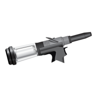
Stroke Adjustment
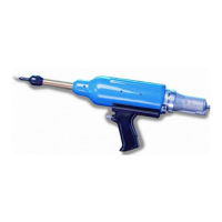
Operating Procedure
Putting into Service
7
All tools are operated with compressed air at an optimum pressure of 5.5 bar. We recommend the use of pressure regulators and
automatic oiling/filtering systems on the main air supply. These should be fitted within 3 metres of the tool (see diagram below) to
ensure maximum tool life and minimum tool maintenance.
Air supply hoses should have a minimum working effective pressure rating of 150% of the maximum pressure produced in the system
or 10 bar, whichever is the highest. Air hoses should be oil resistant, have an abrasion resistant exterior and should be armoured
where operating conditions may result in hoses being damaged. All air hoses MUST have a minimum bore diameter of 6.4 millimetres
or
1
/4 inch.
Read servicing daily details page 10.
• Connect tool to air supply.
• Offer up insert, lip first to drive screw. A light pressure will start the motor and automatically thread the insert up against nose and
stop.
• Insert fastener into application squarely.
• Fully depress trigger. This will both place insert into the application and reverse it off the drive screw.
This adjustment is necessary to ensure optimum insert deformation. It
is suggested, therefore, that a test plate with the same thickness and
hole size as workpiece be used.
If deformation is insufficient, the insert will rotate inside the application.
If deformation is excessive, thread distortion will occur and possibly
drive screw fracture.
The stroke is adjusted by the amount the rear casing 86 is screwed in or
out. To shorten stroke, screw in; to lengthen stroke, unscrew the rear
casing but never more than 5 turns from the fully “IN” position unless
dismantling the tool. Adjust until optimum deformation is obtained.
Lock the stroke set finger 88 into the rear casing.
Item numbers in bold refer to the General Assembly drawing and parts list (pages 14-15).