8
Fitting Instructions
Servicing Instructions
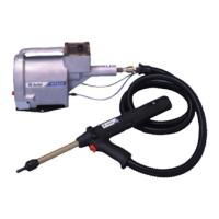
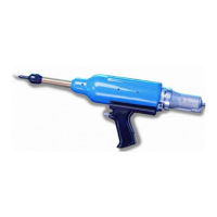
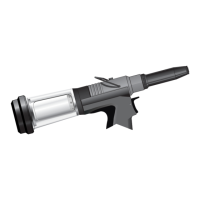
Nose Assemblies
It is essential that the correct nose assembly is fitted prior to operating the tool. By knowing the details of the fastener to be placed,
you will be able to order a new complete nose assembly using the selection tables on page 9.
IMPORTANT
The air supply must be disconnected when fitting or removing nose assemblies unless specifically instructed
otherwise.
Nose assemblies should be serviced at weekly intervals.
• Remove the complete nose assembly using the reverse procedure to the ‘Fitting Instructions’.
• Any worn or damaged part should be replaced by a new part.
• Particularly check wear on drive screw.
• Assemble according to fitting instructions.
* Refers to items included in the 74200 service kit. For complete list see page 11.
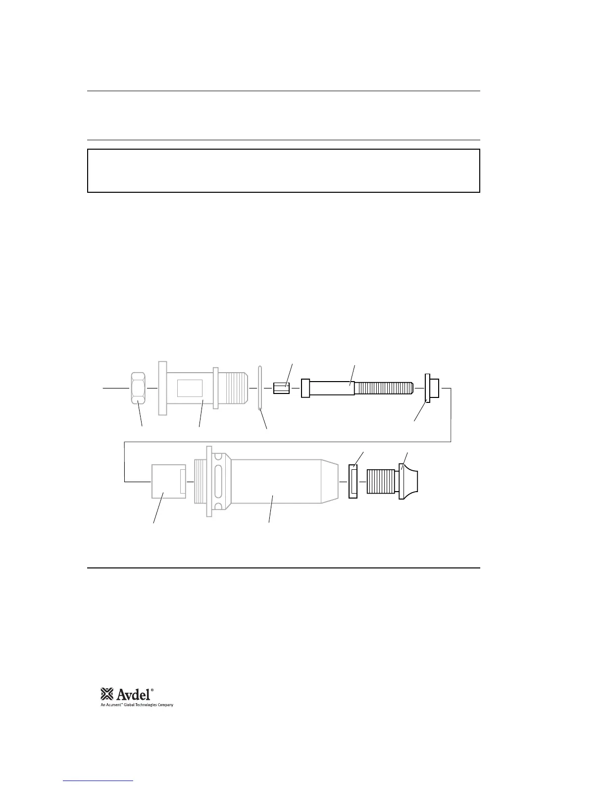
Item numbers in bold refer to illustration below:
• If still fitted remove the nose casing and the adaptor nut.
• Insert drive shaft 4 into spindle.
• Fit drive screw 3 onto drive shaft 4.
• Insert reducing sleeve 5 (if specified) into the adaptor nut.
• Screw the adaptor nut onto the spindle.
• Hold the spindle with a spanner* and tighten the adaptor nut clockwise.
• While holding the adaptor nut with the spanner*, tighten the lock nut anti-clockwise.
• Screw on the nose casing and nose tip 1 with the nose tip lock nut.
• The reverse operation is carried out for equipment removal.
• With tool still disconnected from air supply, screw one insert onto drive screw manually - making sure the insert is flush with the
end of drive screw.
• Set nose tip in exact position and lock nose tip nut clockwise with a spanner*.
• Remove the insert from drive screw.