7
Cable Connections
Connecting Power
NOTE: Do not perform this procedure if the camera is powered through Power over
Ethernet (POE).
If PoE is not available, the camera needs to be powered through the removable power
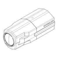
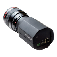
connector block on the camera. Refer to the camera diagrams for the location of the
power connector block.
The camera can be powered from 12 VDC or 24 VAC. The power consumption
information is listed in the camera specifications.
To connect power to the camera, complete the following steps:
1. Remove the power connector block from the camera.
2. Remove the insulation from ¼” (6 mm) of the power wires.
Do not nick or damage the wires.
3. Insert the two power wires into the two terminals on the camera. The
connection can be made with either polarity.
Use a small slotted (5/64” or 2 mm blade width) screwdriver to loosen and
tighten the terminals.
4. Attach the power connector block back into the receptacle on the camera.
Warning — This product is intended to be supplied by a UL Listed Power Unit
marked “Class 2” or “LPS” or “Limited Power Source” with output rated between
12 VDC or 24 VAC, 6 W min. or PoE rated 48 VDC, 6 W min.
 Loading...