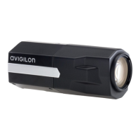
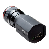
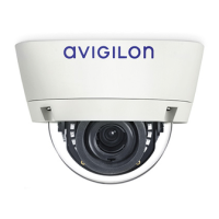
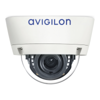
Connecting to Power and External Devices
Important: Be careful not to connect power to the audio input cable, doing so will permanently damage the
camera. Both the audio input cable and auxiliary power cable are brown. To distinguish the auxiliary power
cable, it is labeled AUX PWR and has a thicker gauge.
NOTE: Do not perform the following procedure if Power over Ethernet (POE) is used.
If PoE is not available, the camera needs to be powered through the auxiliary power cables. The camera can be
powered from 12 V DC or 24 V AC. The power consumption information is listed in the product specifications.
To power the camera, connect the two power wires to the brown and blue auxiliary power cables. The
connection can be made with either polarity.
WARNING — This product is intended to be supplied by a UL Listed Power Unit marked “Class 2” or
“LPS” or “Limited Power Source” with output rated 12 VDC or 24 VAC, 13 W min. or PoE rated 48 VDC, 13
W min.
Power supplies and external devices are connected to the camera through the power and I/O cables. The
pinout for the I/O and power cables is shown in the following diagram:
1. Brown — Audio Input
2. Yellow — Audio Ground
3. Green — Audio Output
4. Grey — Relay Ground
5. Red — Relay Input
6. Pink — Relay Output
7. Purple — Reserved cable, do not connect.
Connecting to Power and External Devices 14

 Loading...