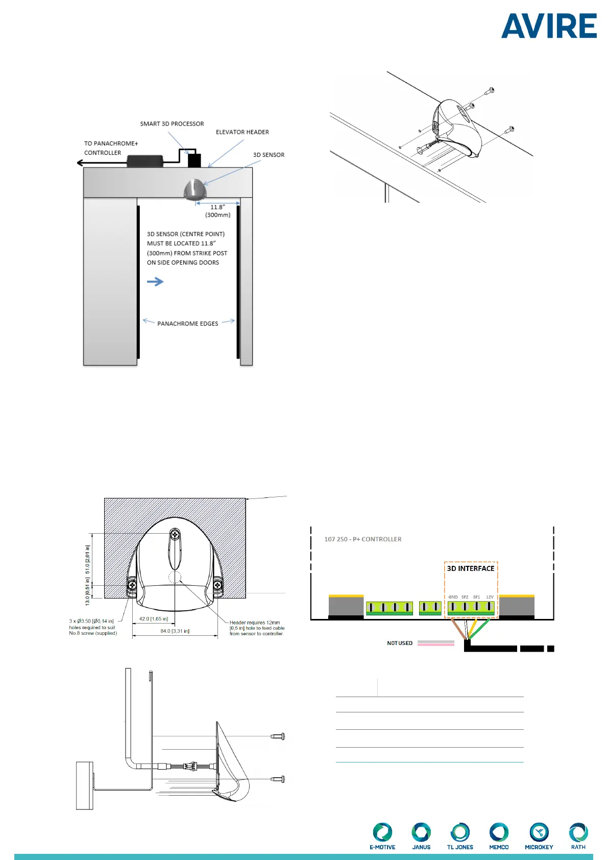
3.1.2 Side Opening Doors
The Smart 3D sensor should be mounted approx.
300mm/11.81” away from the return jamb, on the header
of the elevator car, with the at face of the sensor pointing
outwards from the elevator.
3.2 Position the Smart 3D sensor on the header of
the elevator as shown in Fig. 4. This must be within
19.69”/500mm from the front of the elevator doors.
3.3 Mark o and drill xing and cable holes as per Fig. 5
on the header of the car.
3.4 Connect the extension cable to the connection wire
on the Smart 3D sensor.
3.5 Feed the extension cable and Smart 3D cable through
the cable hole drilled in 3.3 and mount the Smart 3D
(gure 4 and 5) using the screws provided.
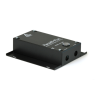
4. Smart 3D processing Box
The Smart 3D processing box is recommended to be
mounted on top of the elevator car and near to the
Panachrome+ controller.
4.1 Lower the elevator car so that it is accessible from the
landing and safe to operate on.
4.2 Gather the extension cable that is connected to the
Smart 3D sensor (3.4) and connect it to the processing
box.
4.3 Find a suitable place to mount the processing box
using either the adhesive tape on the bottom of the box or
use the mounting holes to x the box to the top of the car.
5. Panachrome+ Controller
5.1 Assuming the Panachrome+ controller has already
been installed, connect the Smart 3D processing box using
the 1.9m /6.23ftcable provided (use gure 8 as reference).
Color Function
Green +12VDC
Yellow Output signal for wide lobe (SF1)
White Output signal for close in lobe (SF2)
Brown Ground (0VDC)
6.23ft
Please note that dimensions are shown in metric and imperial
Figure 5
Figure 6
Figure 7
Figure 8
Figure 4
Cable hole