- 12 -
Type of connections
The CAPTURE central control unit has a basic conguration of eight inputs that can be individually programmed as:
- NO (Normally Open),
- NC (Normally Closed), which is the DEFAULT state,
- Inertial Vibration (balance with one 2300 ohm resistor)
- Inertial Roller Shutter (balance with one 2300 ohm resistor)
- Inertial Vibration NC (Normally Closed)
- Inertial Roller Shutter NC (Normally Closed)
- 1R (balance with one 4700 ohm resistor), in this case there will be only the alarm signal of the zone
N.B.:The equipment must be protected by using the TAMPER dedicated line or a different input zone of the control panel, programmed in TAMPER modality.
- 2R (balance with two 4700 ohm resistors), in this case there will be both the alarm signal and the tamper signal of the zone.
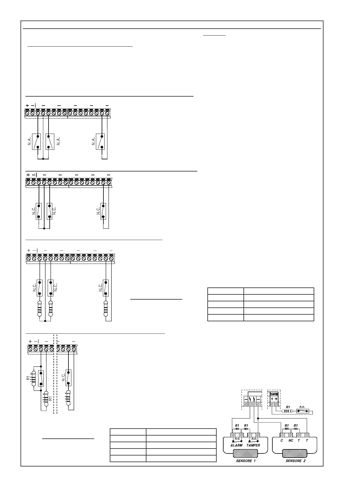
NO Zones (Normally Open Inputs) (NO XSAT36, XSATPW e XSATHP)
NC Zones (Normally Closed Inputs) (NO XSAT36, XSATPW e XSATHP)
Zones 1R (Balanced inputs with one 4700 ohm resistor)
Zones 2R (Balanced inputs with two 4700 ohm resistors)
L2L1 L3 L4
L5 L7
L8
T
This conguration allows only the alarm status of the zone corresponding with the unbalanced
input to be recognised:
L1 - L8: Negative closing of the circuit in inputs from L1 to L8 triggers the alarm of the cor-
responding zone.
T: Negative closing of the circuit of input T (normally used to protect the equipment) triggers
a TAMPER alarm.
L6
L2
L1 L3 L4
L5
L7
L8
T
This conguration allows only the alarm status of the zone corresponding with the unbalanced
input to be recognised:
L1 - L8: Negative closing of the circuit in inputs from L1 to L8 triggers the alarm of the
corresponding zone.
T: Negative closing of the circuit of input T (normally used to protect the equipment) triggers
a TAMPER alarm.
L6
L2
L1 L3 L4
L5
L7
L8
T
R1 R1 R1
L6
This conguration allows only the alarm status of the zone corresponding with the unba-
lanced input to be recognised:
L1 - L8: Negative closing of the circuit in inputs from L1 to L8 triggers the alarm of the
corresponding zone.
T: Negative closing of the circuit of input T (normally used to protect the equipment) triggers
a TAMPER alarm.
Balancing resistance
The colours of R1 terminal resi-
stance are:
R1 4.700 ohm
1) Yellow Value: 4
2) Purple Value: 7
3) Red Number of zeros 2
4) Gold Tolerance: 5%
This conguration allows the central control unit to recognise both tamper and alarm status using the same zone circuit:
L1 - L8: The inputs of the zones programmed in this mode must be terminated with two 4700 ohm resistors. The rst
resistor (in parallel with the alarm contact of the sensor) identies the zone alarm while the second (in series with the
circuit) identies the tampering.
While referring to the gure at the side, when the contact is opened the central control unit detects the general alarm
status of the sensor, while the short circuit or clipping of the input circuit triggers a tamper alarm, even with the system
switched off.
T: The dedicated Tamper line is always balanced with a single termination resistor. The opening or short circuit of
input T (normally used to protect the equipment) triggers a TAMPER alarm.
L2
L1
L8
T
R1
R1
Example:
The connection of two general sensors to two inputs programmed
as Zones 2R is shown by way of example.
Opening of the NC ALARM contact triggers an alarm status.
Opening of the NC TAMPER or a short circuit triggers the tamper
alarm of the corresponding input zone.
Balancing resistance
The colours of R1 terminal
resistance are:
R1 4.700 ohm
1) Yellow Value: 4
2) Purple Value: 7
3) Red Number of zeros 2
4) Gold Tolerance: 5%